Installation/setup, Warning, Unit assembly – Hot Max Torches 250WFG User Manual
Page 8: Welding set up
Installation/Setup
KDAR Company
7
Unit Assembly
1. With something to prevent scratching under the unit,
tip the welder forward onto its face.
2. Using the six 6mm x 12mm bolts and 6mm lock wash-
ers, attach the tank deck to the welder as shown in fig-
ure 5.
3. Slide the wheel axle through the two holes in the tank
deck, slide one washer on each end followed by a 10”
wheel and a second washer. Then place a cotter pin
through the hole at each end of the axle and bend it to
hold in place.
4. Attach a plug rated for 50 Amps/250 Volts (not includ-
ed) to the end of the power cord according to the in-
structions supplied with the plug. Note: Green jacketed
wire is neutral (ground).
Warning
Always unplug the welder before connecting or disconnecting accessories.
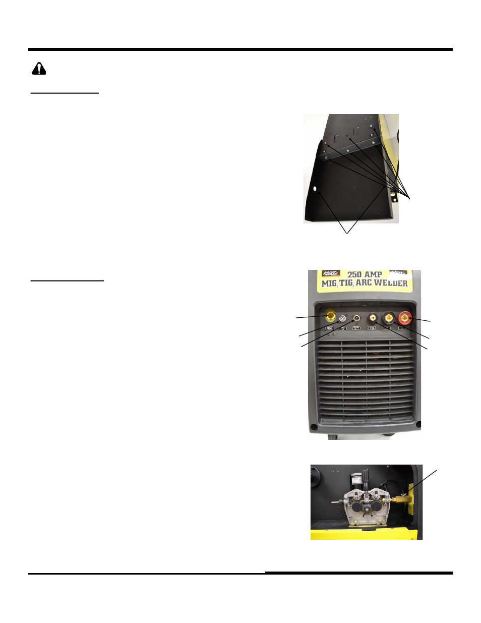
Welding Set Up
Arc Welding
1. Insert the male connector on the electrode holder cable
into the positive (+) quick connect port (1). (Figure 6)
2. Insert the male connector on the ground clamp cable into
the negative (-) quick connect port (2). (Figure 6)
MIG Welding
1. Insert male connector on the ground clamp cable into the
negative (-) quick connect port (2). (Figure 6)
2. Insert the male connector on the gun cable into the gun
cable connection port (3), labeled “MIG.” Figure 6)
3. With the connector all the way in the connector block,
tighten the wing nut (4) to secure the gun. (Figure 7)
4. Connect the gun lead terminal to the gun lead connector
(5). (Figure 6)
TIG Welding
1. Insert the male connector on the ground clamp cable into
the positive (+) quick connect port (1). (Figure 6)
2. Connect foot pedal lead terminal A to the foot pedal lead
connector A (5). (Figure 6)
3. Connect foot pedal lead terminal B to foot lead connect B
(6). (Figure 6)
4. Connect TIG gun torch assembly to TIG connector (7).
2
3
Figure 5
Figure 6
1
2
3
4
5
Figure 7
6
7