Transport wheels – Summers 3-Rank Superweeder User Manual
Page 21
3-3
Use CAUTION when making manual height adjustments. For Safety purposes, block equipment while working on it.
On the center two sections only, move the lower stop bolt and bushing to the front hole (Fig. 12). This will allow the sections
to raise more evenly.
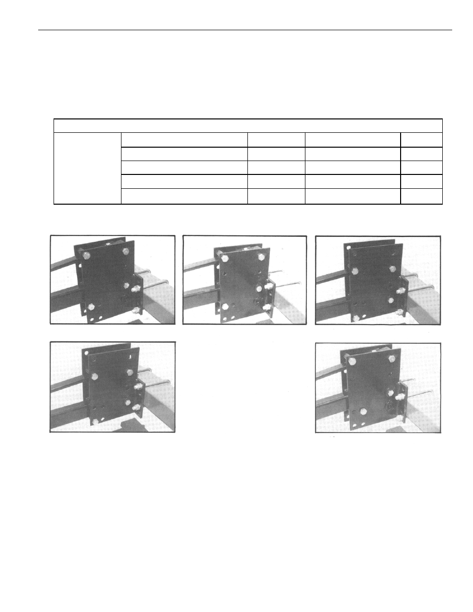
To compensate for various soil conditions and tooth wear, the sections can be mounted in four different positions as shown
below.
TRANSPORT WHEELS
Install transport wheels as shown in figures 1 and 13. Secure with two 5/8” x 5-1/2” bolts, lock washers and nuts.
NOTE: Transport wheel brackets are made for left and right and are not interchangeable.
IMPORTANT: The positioning of the transport wheel assemblies on the wing tubes of the machine is very critical in determin-
ing hitch weight. Moving transport wheel assemblies forward will increase hitch weight and moving rearward will decrease
hitch weight. See the “Warning Regarding Machines With Negative Hitch Weight” on page 1-2 for more information.
SECTION 3 – SET-UP INSTRUCTIONS — SUPERHARROW
Height Adjustment
Suggested
Lift Arm Center
U-Bolt Plate Lift Arm / Spring Flat
Ref.
Initial Setting
3” Above Drawbar Center
Up
Up
Fig. 8
1-1/2” Above Drawbar Center
Down
Up
Fig. 9
Even With Drawbar Center
Up
Down
Fig. 10
1-1/2” Below Drawbar Center
Down
Down
Fig. 11
Fig. 8
Fig. 9
Fig. 10
Fig. 11
Fig. 12