Zoo Med Turtle Clean™ 30 External Canister Filter User Manual
Page 2
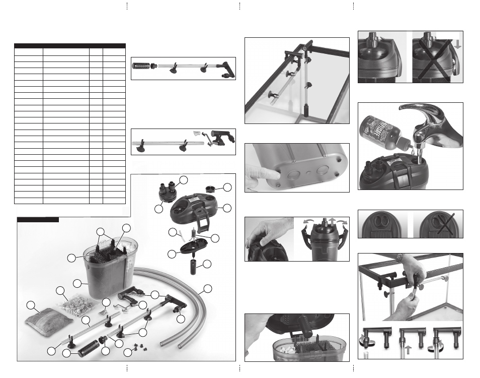
LETTER CODE
DESCRIPTION
QTY.
PART NO.
A
FILTEr CANISTEr
1
PTC-30
B1
COArSE SPONGE
1
PTC-31
B2
FINE SPONGE
1
PTC-32
C
IMPELLEr COvEr
1
PTC-33
D
IMPELLEr
1
PTC-34
E
SCrEw NUT
4
PTC-35
F
FILL CAP
1
PTC-06
G
CLIP AND SUCTION CUP
5
PTC-36
H
INTAKE STrAINEr
2
PTC-37
I
HArD ELBOw UNIT
2
PTC-38
J
CLEAr PLASTIC PLUG
1
PTC-46
K
FILTEr HEAD
1
PTC-39
L
FLOw DIvErTEr
1
PTC-10
M
rUBBEr ELBOw
1
PTC-11
N
INTAKE TUBE (rIGID)
1
PTC-40
P
SPrAy BAr (rIGID)
1
PTC-41
Q
CErAMIC MEDIA
1
PTC-14
r
INTAKE/OUTLET TUBING (FLExIBLE)
2
PTC-42
S
CHAMBEr DIvIDEr
2
PTC-43
T
AIr vENT TUBE
1
PTC-17
U
HOSE CONNECTING DEvICE
1
PTC-44
v
ADAPTEr
1
PTC-45
w
rUBBEr FEET
4
PTC-21
x
ACTIvATED CArBON BAG
1
PTC-18
2. intake Unit aSSeMblY:
Attach the
adapter (v) to the intake strainer (H), and insert one end of the
intake tube (N) into the end of the adapter (v).
Mount the two clips to the
suction cups (G), and attach the clips to the intake
tube (N).
Thread the
screw nut (E) onto the hard elbow unit (I), and insert the other
end of the
intake tube (N) into the hard elbow unit (I) as shown in image 1.
Note: The hard elbow units (I) contain the orange flow control adjustment
devices. These should be set at “MAX” during initial startup.
3. OUtlet Unit aSSeMblY:
Mount the
rubber elbow (M) onto the other hard elbow unit (I), and assem-
ble the
spray bar (P), or the flow diverter (L) according to your needs.
If using the
spray bar (P), insert the clear plastic plug (J) into the end of
the spray bar, and attach the bar securely to the tank wall with two clips and
suction cups (G).
Attach the remaining clip and
suction cup (G) to the hard elbow unit (I),
allowing the hard elbow unit on the outlet side to be secured to the tank.
Thread the
screw nuts (E) onto the outlet side hard elbow unit (I) as show
in image 2.
Thread the remaining
screw nuts (E) to the IN/OUT nozzles of the hose con-
necting device (U) as shown below in the parts diagram.
Clean the wall of your turtle’s tank and attach the intake and outlet units as
shown in image 3.
Note: The photo shows the spray bar on the intake unit, but you may use
the flow diverter instead of the spray bar if desired.
4. Filter aSSeMblY:
Insert the four
rubber feet (w) into the holes on the bottom of the filter can-
ister (A), as shown in image 4.
Open the filter by releasing the clips on the
filter head (K) from above and
pulling them outward. When the clips are pulled completely outward, the filter
head will lift off of the
filter canister (A) slightly and disengage from its seat
as shown in image 5.
Rinse the
Activated Carbon Bag (x) under running water and insert it into the
empty side of the
filter canister (A).
Note: Do not open the activated carbon bag.
Remove the
ceramic media (Q) from the plastic bag, rinse under running
water, and add to the filter canister on top of the carbon bag.
Note: Do not overfill with ceramic media or you will not be able to reattach
the filter head. Save any remaining ceramic media for future use.
Reattach the
filter head (K), making sure that the fill cap (F) is above the
side with the
ceramic media (Q), and the hose connecting device (U) is
above the side with the
coarse sponge (B1), as shown in image 6.
Press the filter head back onto the
filter canister (A), and latch the two clips
by hooking them onto the filter canister and pressing inward until you hear
them “snap” into place.
Unscrew the
fill cap (F) by turning it counter clockwise as shown by the
arrows on the cap. Fill the canister completely with dechlorinated water.
Note: use Zoo Med’s REPTISAFE to dechlorinate the water.
Replace the fill cap, making sure that it locks in place and that the cap is in
the locked position as shown in image 9. If not locked in place, your filter may
not operate properly.
Push the
intake and outlet tubing (r) onto the hard elbow units (I) and lock
them with the screw nuts as shown in image 10.
1. aSSeMblY inStrUctiOnS:
Remove contents from box and inspect to make sure that there are no missing
parts (see parts diagram). Refer to the parts diagram to identify parts men-
tioned in the following assembly instructions.
Replacement parts are available online by visiting the “STORE” section of our
website at
www.zoomed.com, or by contacting customer service.
partS liSt
partS diagraM
IMAGE 3
IMAGE 4
IMAGE 5
IMAGE 6
IMAGE 7
IMAGE 8
IMAGE 9
IMAGE 10
IMAGE 1
IMAGE 2
l
J
p
h
V
n
X
Q
e
W
g
r
i
M
b
S
b
a
1
2
Not completely
fastened
k
F
e
U
t
c
d
h