Serial communications – High Country Tek HFS-J-Bus User Manual
Page 14
Electronic Controller Solutions for the Global Fluid Power Industry
Hydraulic Fan System Controller with SAE J1939 Interface
HFS-J User Guide
Part No:-
021-00158 Rev C
HFS-J Hydraulic Fan System Controller User Guide
Page | 14
Serial Communications:
HFS-J monitoring, health checks, diagnostics and set-up can be accessed through the supplied GUI. This program will
operate on PC using a based Windows® operating system and is password protected to maintain module parameter
integrity by only allowing authorized users to access different levels of the controller settings.
The interface is designed to be simple to use and follows the familiar Windows® menu format with drop down option
screens to select the various options available at the user level allowed.
Explanations of the screens are covered in detail, later in this guide.
Once the PC has been connected to a ‘live’ HFS-J, and the GUI program started, a free communications port will be
either automatically allocated ( Windows® XP ) or will have to be manually chosen from a menu that will be displayed.
Users running a computer without a 9 pin serial port MUST use HCT approved RS232/USB adaptor:-
Part Number
Notes
108-00119
CE certified
RoHS compliant
After communications have been established, the user will be presented with the initial information screen that will
give all the basic information needed to assess the health of the system.
Real time graphing is available here to monitor a wide range of items ( selectable from a drop down and select list )
and for remote diagnostics, a ‘Data Log’ button will start a Windows Excel file that can be used as a monitor for
comparison to other logged charts during the system’s life or can be E-mailed to an engineering source if there is a
problem for diagnosis.
Passwords protect the settings of the module at all times and are needed to make any changes to the operational
parameters.
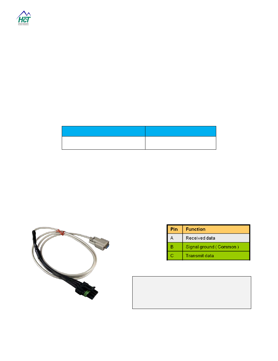
RS232 Serial Connection Cable: Part No- 999-10075 ( see page 32 of this manual )
NOTE:
The 4 pin shroud Weatherpack connector from the
controller has MALE pins, therefore the mating cable
needs to terminate in a Tower Weatherpack connector
with FEMALE pins.