Application examples – High Country Tek HFS-J-Bus User Manual
Page 10
Electronic Controller Solutions for the Global Fluid Power Industry
Hydraulic Fan System Controller with SAE J1939 Interface
HFS-J User Guide
Part No:-
021-00158 Rev C
HFS-J Hydraulic Fan System Controller User Guide
Page | 10
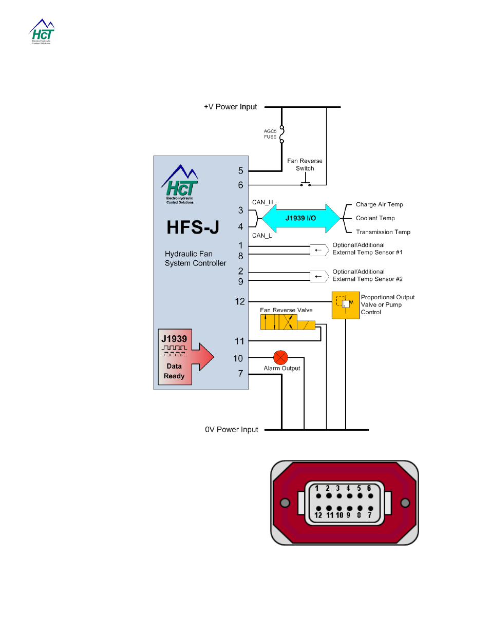
Application Examples:
NOTE:-
Controller MUST have
in-line fuse fitted by
user in +V Power Input
for system protection.
Pin 1:- Thermistor #1 +signal input.
Pin 2:- Thermistor #2 +signal input.
Pin 3:- CAN_H Input ( J1939 )
Pin 4:- CAN_L Input ( J1939 )
Pin 5:- +Vin 9 to 32VDC Power supply Input
Pin 6:- Reverse fan input ( Momentary )
Pin 7:- 0V power input ( Common )
Pin 8:- 0V—Signal common #1
Pin 9:- 0V—Signal common #2
Pin 10:- Alarm output drive ( 3A max sourcing )
Pin 11:- Reverse valve output drive ( 3A max sourcing )
Pin 12:- Proportional valve output ( 3A max sourcing )
NOTE:-
View looking at 12 way male connector on
HFS - J
controller -
DTF15-12PB