0 troubleshooting, 0 specifications – Hawkeye Goshawk User Manual
Page 4
Hawkeye Industries Inc.
1-800-910-4295 www.hawk-eye.com
4
REVISION D0, MARCH 2014
5.3 REPLACING THE TRANSITION COUPLER
5.3.1 TOOLS REQUIRED
Allen Keys
.................................................................................. 3 / 32 in
5.3.2 REMOVE OLD TRANSITION COUPLER
1.)
Follow Section 5.1.2 to remove the Goshawk from the Gauge Head
2.)
Back out and remove the set screw holding the Transition Coupler [D] in
Place.
3.)
Set the old Transition Coupler [D] Aside.
5.3.3 INSTALL NEW TRANSITION COUPLER
4.)
Slide the new Transition Coupler [D] onto the Operator Shaft [J], ensuring
the tapped hole for the set screw aligns with the flat on the Operator shaft [J].
5.)
Reinstall the Set Screw with the 3 / 32 in Allen Key and secure the coupling
[J] to the Shaft.
6.)
Follow Section 3.3 onward to reinstall the transmitter.
FIGURE 15
REMOVING THE TRANSITION COUPLER
[STEPS 2.) TO 6.)]
CAUTION: AFTER REPLACING THE TRANSITION COUPLER, IT IS VITAL THAT THE
PREPARATION AND MOUNTING DIRECTIONS OF SECTION 3.3 ONWARD ARE
FOLLOWED, OTHERWISE DAMAGE TO THE ENCODING POTENTIOMETER WILL
OCCUR.
5.4 INSTALLING OPTIONAL REDUCING
TRANSMISSION
To change the operating range of a Goshawk Transmitter (see 6.4) from a standard GH
I to GH II or GH III, a reducing transmission [M] – [P] can be installed after the fact.
This procedure outlines converting a GH I to a GH II or GH III.
NOTE: THIS PROCEDURE IS BEST PERFORMED WITH THE TRANSMITTER OFF THE
TANK, AND IN A CONTROLLED, INDOOR ENVIRONMENT.
5.4.1 TOOLS REQUIRED
Allen Keys
.............................................................. 1 / 16 in and 3 / 32 in
Screw Driver
....................................................... Phillips or Blade (will vary)
Wrench
..................................................................................... 1 /2 in
Retaining Ring Pliers .................................................................. ½ External Shaft
5.4.2 PARTS REQUIRED
GH II or GH III Transmission Assembly
5.4.3 REMOVE COVER
1.)
Follow Section 5.1.2 to remove the transmitter from the Gauge Head.
2.)
Ensure the Goshawk is not energized.
3.)
Remove the cover [A], per Section 5.1.3
5.4.4 FREE THE OPERATOR SHAFT
4.)
Follow Section 5.3.2
5.)
Remove the 1 / 4 External Retaining Ring securing the operator shaft [J] in
the operator bushing [L] using the retaining ring pliers.
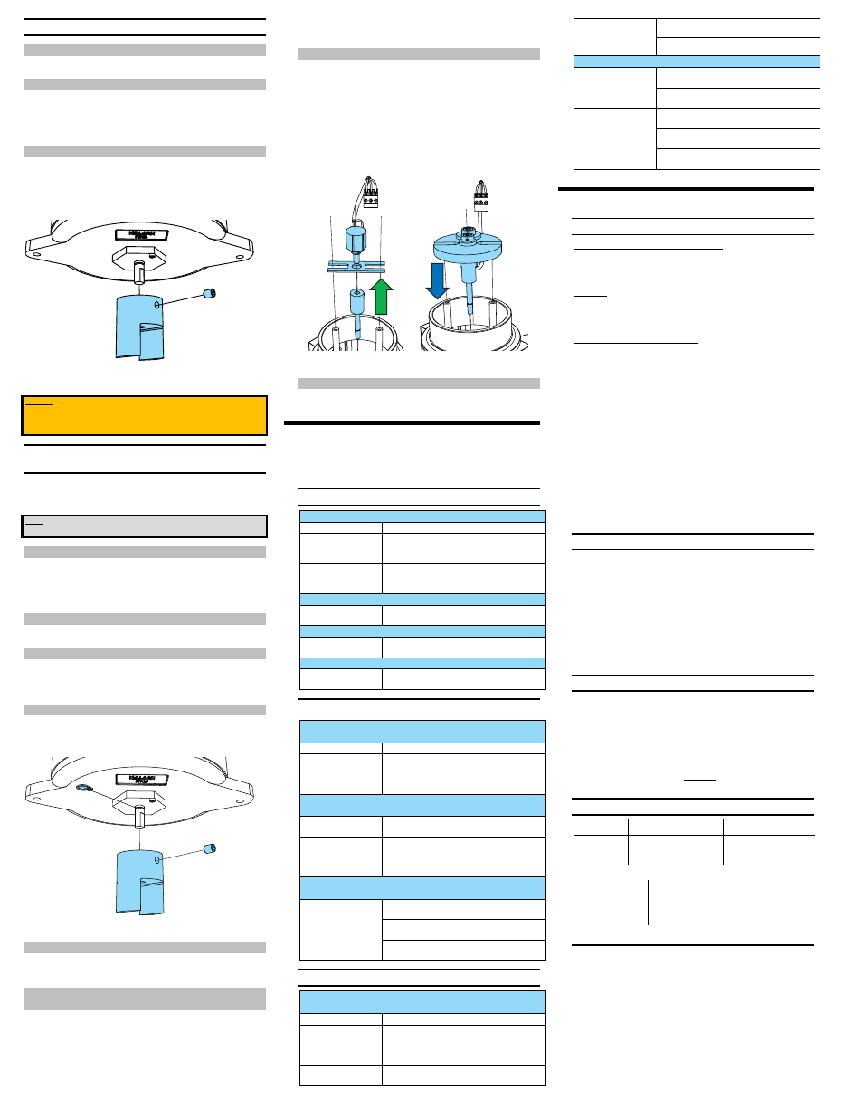
FIGURE 16
REMOVING TRANSITION COUPLER AND FREEING
OPERATOR SHAFT
[STEP 5.)]
5.4.5 REMOVE PCB & POTENTIOMETER
6.)
Follow Section 5.1.4
7.)
Follow Section 5.2.3
5.4.6 INSTALL POTENTIOMETER ON TRANSMISSION
CHASSIS
8.)
Thread the Encoding Potentiometer [G] into underside of the transmission
chassis [O] so the Encoding Potentiometer [G] extends through the chassis
[O] and is on the same side as the small gear [N]. Refer the figure in to
Section 2.4.
9.)
Use the 1/16 Allen key to back out slightly the set screw from the large gear
[M]. Slip the large gear [M], hub up, onto the potentiometer shaft [G], and
secure into place by with the 1/16 in Allen key. Ensure the gears [M] & [N]
are meshing and moving freely before moving on.
5.4.7 REASSEMBLE TRANSMITTER
10.)
Connect the Operator Shaft [J] from Section Error! Reference source not
found. to the transmission centre axel [P], and tighten the set screws with the
3 / 32 Allen key.
11.)
Drop the Operator [J] / Transmission assembly [M] – [P] down through the
operator bushing [L], and replace the retaining ring and transition coupling
[D] from Section 5.4.4.
12.)
Make sure the cable running from the Encoding Potentiometer [G] is not
rubbing or binding on the transmission chassis [O] or gears [M] – [N].
13.)
Reattach the PCB [H] to the standoffs [K], from Section 5.4.5. Reconnect the
Orange Power [E] and Grey Encoding [F] Potentiometer terminal plugs.
FIGURE 17
REMOVING THE HCLIP AND INSTALLING THE REDUCING
TRANSMISSION
5.4.8 INSTALL AND CALIBRATE
14.)
Return to Section 3.3 and follow the installation and calibration steps.
6.0 TROUBLESHOOTING
Use the following troubleshooting steps to solve most Goshawk Transmitter problems.
If you cannot solve the problem after following this guide, call us at 1-800-910-4295
for technical support.
6.1 CALIBRATION PROBLEMS
Problem: Current does not increase beyond 3.1 mA
Symptom of
Solution:
R20 (Zero) Trimmer [V]
out of operating range
Keep Turning R20 (Zero) [V] CLOCKWISE to increase
current output. Note, output may momentarily
decrease as the trimmer comes into operating range.
Damaged Encoding
Potentiometer [G]
[ Over turned ]
Replace Encoding Potentiometer [G], per Section
5.2.
Problem: Cannot get current below 4.0 mA when adjusting zero
Span Sensitivity Setting
too high
Decrease Span Sensitivity (Increase Resistance of
R10 [S] and R13 [R]). Refer to Section 4.1.
Problem: Cannot get current lower than 20 mA when adjusting span
Span Sensitivity Setting
too high
Decrease Span Sensitivity (Increase Resistance of
R10 [S] and R13 [R]). Refer to Section 4.1.
Problem: Cannot get current up to 20 mA when adjusting span
Span Sensitivity Setting
too low
Increase Span Sensitivity (Decrease Resistance of
R10 [S] and R13 [R]). Refer to Section 4.1.
6.2 NONSENSE READOUTS
Problem: Current output drops out to less than 4mA but resumes back
as float traverses from empty to full
Symptom of:
Solution:
Damaged Encoding
Potentiometer [G]
[ Dead Spot ]
Replace Encoding Potentiometer [G], per Section
5.2.If High agitation is a recurrent situation in your
tank, a high-agitation coupling is available to limit
wear.
Problem: Current output increases as float moves from empty to full,
but stops changing at some midpoint between empty and full.
Insufficient input
voltage
Ensure the voltage, measured at the transmitter in
TANK FULL CONDITION is at least 13 VDC.
Damaged Encoding
Potentiometer [G]
[ Dead Spot ]
Replace Encoding Potentiometer [G], per Section
5.2.If High agitation is a recurrent situation in your
tank, a high-agitation coupling is available to limit
wear.
Problem: Current drops as tank fills / current increases as tank
empties
Reversed Installation
Ensure Gauge Head Installed Properly and in correct
orientation, Refer to the figures in Section 1.3.
Ensure Gauge Head Cables wrapped in factory
standard condition. Refer to Section 3.3.1.
Ensure
Goshawk
installed
on Atmospheric Side of
Gauge Head.
6.3 MECHANICAL PROBLEMS
Problem: Float and Indicator moving, Goshawk working, but
periodically getting stuck due to catching or rubbing
Symptom of:
Solution:
Transmitter
Misalignment on Gauge
Head
Make sure the alignment steps in Section 3.3 have
been followed.
Replace Electronic Cover Plate
Cable rubbing on gauge
head
Ensure Gauge Head Installed Properly and in correct
orientation, Refer to Section 1.3.
Misaligned cable Reel: Replace reel.
Problem: Float and Indicator not moving at all, Goshawk not working
Exceeding Encoding
Potentiometer Travel
Ensure the Goshawk Operating Range is appropriate
for your application. Refer to 7.4.
Convert GHI to GHII or GHIII & Replace Encoding
Potentiometer [G]
Reversed or Partially
Reversed Installation
Ensure Gauge Head Installed Properly and in correct
orientation, Refer to 1.3.
Ensure Gauge Head Cables wrapped in factory
standard condition. Refer to 3.3.1.
Ensure
Goshawk
installed
on Atmospheric Side of
Gauge Head.
7.0 SPECIFICATIONS
7.1 MECHANICAL INPUT:
Rotational Displacement from Gauge Head Cable Reel
Goshawk I
.....................................................
3600° Max (10 revolutions)
Goshawk II
.....................................................
5400° Max (15 revolutions)
Goshawk III
.....................................................
9000° Max (25 revolutions)
Gear Ratios:
Goshawk I
..........................................................................................
1:1
Goshawk II
..........................................................................................
3:2
Goshawk III
..........................................................................................
5:2
Distance Traversed per Gauge Head Rotation:
Redtail
.................................................................................... 36.1 in
Roadside
....................................................................................
17.3
in
Mechanical Input Notes:
1.)
The encoding potentiometer is always limited to 3600° of rotation (10
revolutions), and has hard stops at full CCW (0°) and full CW (3600°)
positions. The extended rotational displacement of the Goshawk II and
Goshawk III is achieved using an internal reducing transmission installed
between the operator shaft and encoding potentiometer.
2.)
Turning the encoding potentiometer beyond its Full CCW to Full CW (0° to
3600°) range will cause irreversible damage to the internal resistive
elements, and will render the transmitter inoperable. Although the encoding
potentiometer has hard stops at the limits of its range, force and leverage
from the cable reel is often enough to overturn the encoding potentiometer.
3.)
The values provided above are absolute maximums. For long life and
reliability of the Goshawk Transmitter, it is recommended that only 80% to
90% of the rotation displacement be utilized.
7.2 ELECTRICAL INPUT:
Electrical Input ........................................ 13 to 24 VDC TWO-WIRE LOOP POWER
Electrical Input Notes:
1.)
13 V is the minimum required voltage to operate the transmitter, if no other
devices are on the loop. If less than 13 V is available to the transmitter, the
output may appear to work for low current outputs, but will drop out as the
current increases.
2.)
24 V is the recommended maximum voltage to operate the transmitter.
Transients up to 40 V may be non-injurious to the electronics, but always
confirm transmitter operation following an over voltage.
3.)
The Goshawk Transmitter will not work with mains or AC power.
7.3 ELECTRICAL OUTPUT:
Current output .................................................................................... 4 to 20 mA
Power Consumption: ........................................................................... 0.5 W max
Electrical Output Notes:
1.)
Load Resistance (R
L
), including line resistance, shall be chosen such that the
supply voltage (V
S
) between the (+) and (-) terminals on the Goshawk
remains between 13 and 24 VDC through the 4- 20 mA operating range.
|
13
20
Ω
7.4 OPERATING RANGES
Redtail With:
Absolute Height
Recommended Height
GH I
8.2 m [27 ft]
7.3 m [24 ft]
GH II
12.8 m [42 ft]
11.9 m [39 ft]
GH III
21.9 m [72 ft]†
21.0 m [69 ft]†
† Goshawk range exceeds maximum gauge head range.
Roadside with:
Absolute Height
Recommended Height
GH I
3.7 m [12 ft]
3.4 m [11 ft]
GH II
6.1 m [20 ft]
5.5 m [18 ft]
GH III
10.4 m [34 ft]†
10.1 m [33 ft]†
† Goshawk range exceeds maximum gauge head range.
7.5 ACCURACY & ERROR
Output non-linearity: ........................................................................... 0.01% Max
Output Error:
.........................0.13% Full Scale @25°C +( Gauge Error x M)
Gauge Error:
Redtail:
........................................
±
0.06 Reel Revolutions (± 2.1 in.)
Roadside:
.......................................
±
0.07 Reel Revolutions (± 1.2 in.)
Multiplier:
Goshawk I ................................................................................ M = 1.0
Goshawk II ............................................................................... M = 1.5
Goshawk III .............................................................................. M = 2.5