Hawkeye Goshawk User Manual
Page 2
Hawkeye Industries Inc.
2
Loop Power Connections
After removing the transmitter cover, the PCB will be visible.
Run the conductors from the conduit port into the transmitter body, and
connect the positive lead from your PLC or Process Meter to the (+) termi-
nal, and the negative lead to the (-).
A Ground or Shield termination (S) is also provided for convenience.
Remove the transmitter cover to expose the PCB and wiring connections.
6
5
REDTAIL SYSTEM
ROADSIDE SYSTEM
GOSHAWK
Calibration
Power up the PLC or loop calibrator. Adjust the R20 (Zero) trimmer (high-
lighted) to achieve a 4 mA output. Turn the trimmer clockwise to increase
the output value, counterclockwise to decrease. If the zero does not in-
crease above 3.5 mA, this is indicative of a damaged potentiometer, see
Section 7.1 Operating and Troubleshooting Guide.
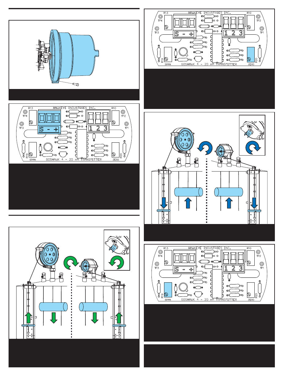
If not already in place, put the gauging system into the TANK EMPTY PO-
SITION, noting the direction of travel of the highlighted items. If the tank
is in-service, see Section 3.3.3 and 4.2 in the Operating and Trou-
bleshooting Guide.
7
REDTAIL SYSTEM
ROADSIDE SYSTEM
GOSHAWK
Put the gauging system into the TANK FULL POSITION, noting the direc-
tion of travel of the highlighted items.
9
8
Adjust the R19 (Span) trimmer (highlighted) to achieve a 20 mA output.
Turn the trimmer clockwise to increase the output value, counterclockwise
to decrease. If the span remains below 20 mA, or remains above 20 mA,
this is indicative of problems with the span sensitivity. Refer to Section
4.1 in the Operating and Troubleshooting Guide.
Reinstall the cover, and the transmitter is ready for service.
Please refer to the Operations and Troubleshooting Guide for more de-
tailed notes on installation, calibration and non-standard configurations.
10