7100 leak detect stik™ data sheet, Dimension drawing, Part numbering – AMETEK 7100 Leak Detect Stik User Manual
Page 3
3
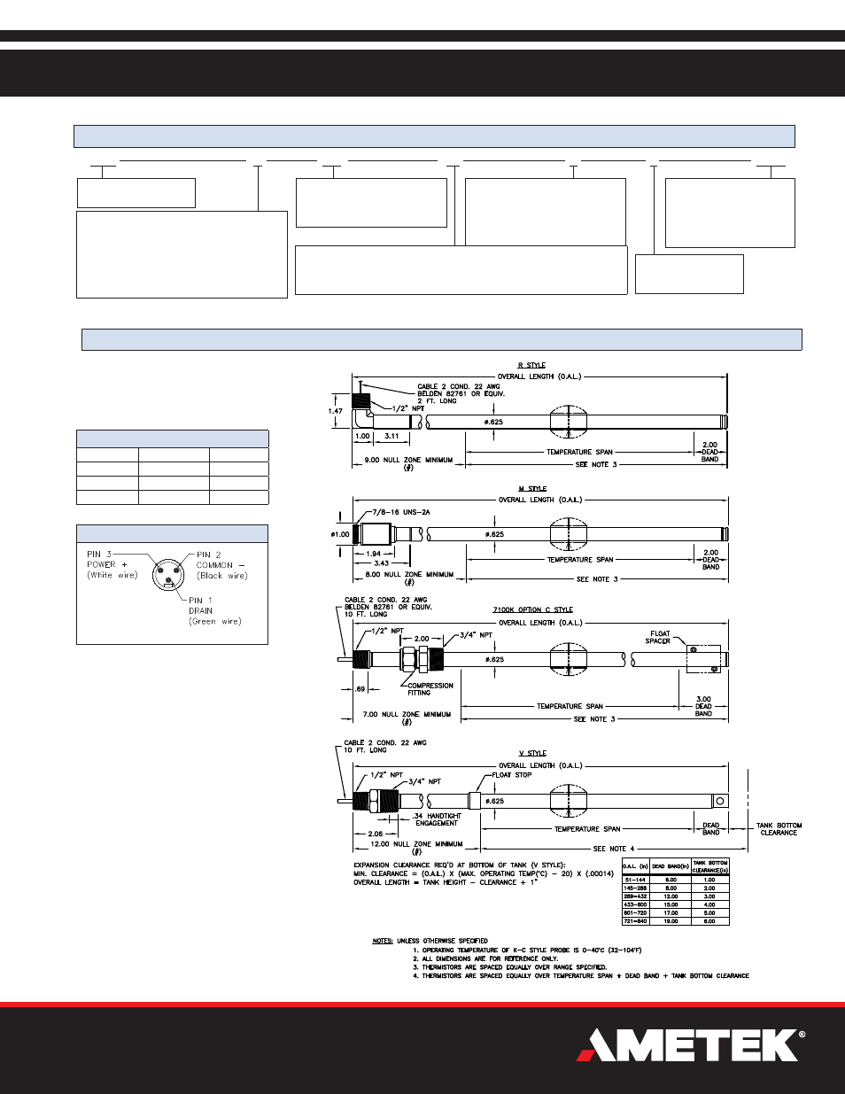
Dimension Drawing
7100
M
R5
F
# of Float Outputs
F1 = One float output.
F2 = Two float output.
Liquid Level Sensor
PPM Output
Number of Thermistors
R1 = Single temperature sensor, 18” from bottom of sensor. For V Style, consult factory.
T1 = Single temperature sensor, 4” from bottom of sensor. For V Style, consult factory.
R5 = Five temperature sensors spaced equally in temperature span.
Connector Style
M = Stainless steel tube with mini-connector.
R = Stainless steel tube with right angle NPT fitting. *
V = PVDF flexible tube with male NPT conduit fitting. *
K = PVDF semi-flexible tube, limited temperature range
0 to 40ºC (Tank mounting method must be option C). *
*R, V & K - 2’ PVC jacketed Teflon insulated wires.
Part Numbering
048
Temperature Span
Insert temperature span in whole
inches. Enter as a three-place number.
Example: A 48” span enters as 048.
X
Tank Mounting Method
X = None.
C = Limited temperature range with
compression fitting.
B = Fixed bottom probe, consult factory.
R = Replacement probe
LXXX
Overall Length
Insert overall length in inches
in place of XXX. Data below
includes nominal null and dead
zones. Longer custom lengths
are available in 1’ increments.
R, K & V Styles Wiring
Signal Name Mating Cordset
Pigtail
Drain
Green
Drain
Common -
Black
Black
Power +
White
Red
M Style Wiring
Install per installation
drawing No. E0234300
7100 Leak Detect Stik™ Data Sheet