4 manual control device, Operating and installation instructions temptrol – ARI Armaturen TEMPTROL 774 EN User Manual
Page 11
Rev. 0040702000 1011
Page 29
Operating and installation instructions
TEMPTROL
®
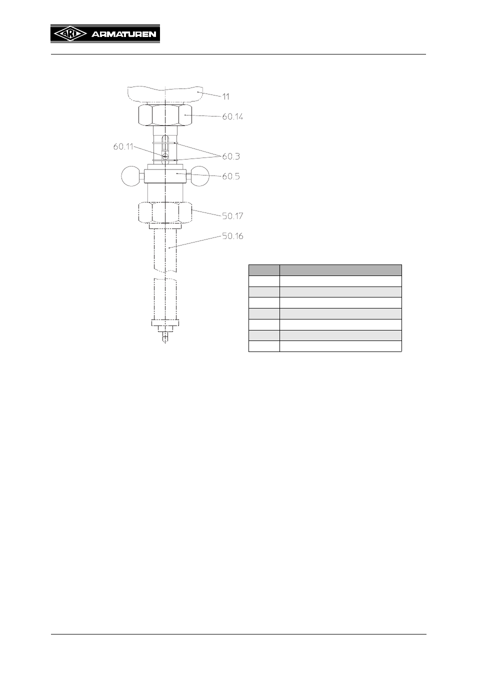
5.4 Manual control device
- The manual control device is installed between the valve (pos. 11) and the actuator
(pos. 50.16) of the thermal control valve (Fig. 5).
- Note, that here also the sealing is only metallic, no extra gasket!
- The connecting nut (pos. 60.14) is fastened with about 100 Nm to the valve (pos. 11), the
actuator (pos. 50.16) with about 50 Nm to the manual control device.
In the following, a setting example is shown for a closing valve:
- Turn the adjusting ring (pos. 60.5) clockwise till the valve (pos. 11) is closed (mechanical
endpoint). The upper securing ring (pos. 60.3) is put in line with the notch of the pin
(pos. 60.11).
- Now turn the adjusting ring (pos. 60.5) anti-clockwise, till the valve (pos. 11) is full open
(max. flow). The bottom securing ring (pos. 60.3) is put in line with the notch of the
indicator pin (pos. 60.11). In the system you can then see the lift over the open and closed
position between the securing rings (pos. 60.3).
- Note, that when working the adjusting ring (pos. 60.5) must be in the opening position of
the valve; closed valve can’t be opened through the thermal controller!
Pos.
Designation
11
Bonnet (valve)
50.16
Actuator
50.17
Connecting nut (actuator)
60.3
Securing ring
60.5
Adjusting ring
60.11
Pin
60.14
Connecting nut
Fig. 5