ARI Armaturen STEVI 446 EN User Manual
Page 15
Rev. 0040301000 0410
Page 15
Operating and installation instructions
Str. thr. control valves - STEVI
®
440 / 441, 445 / 446
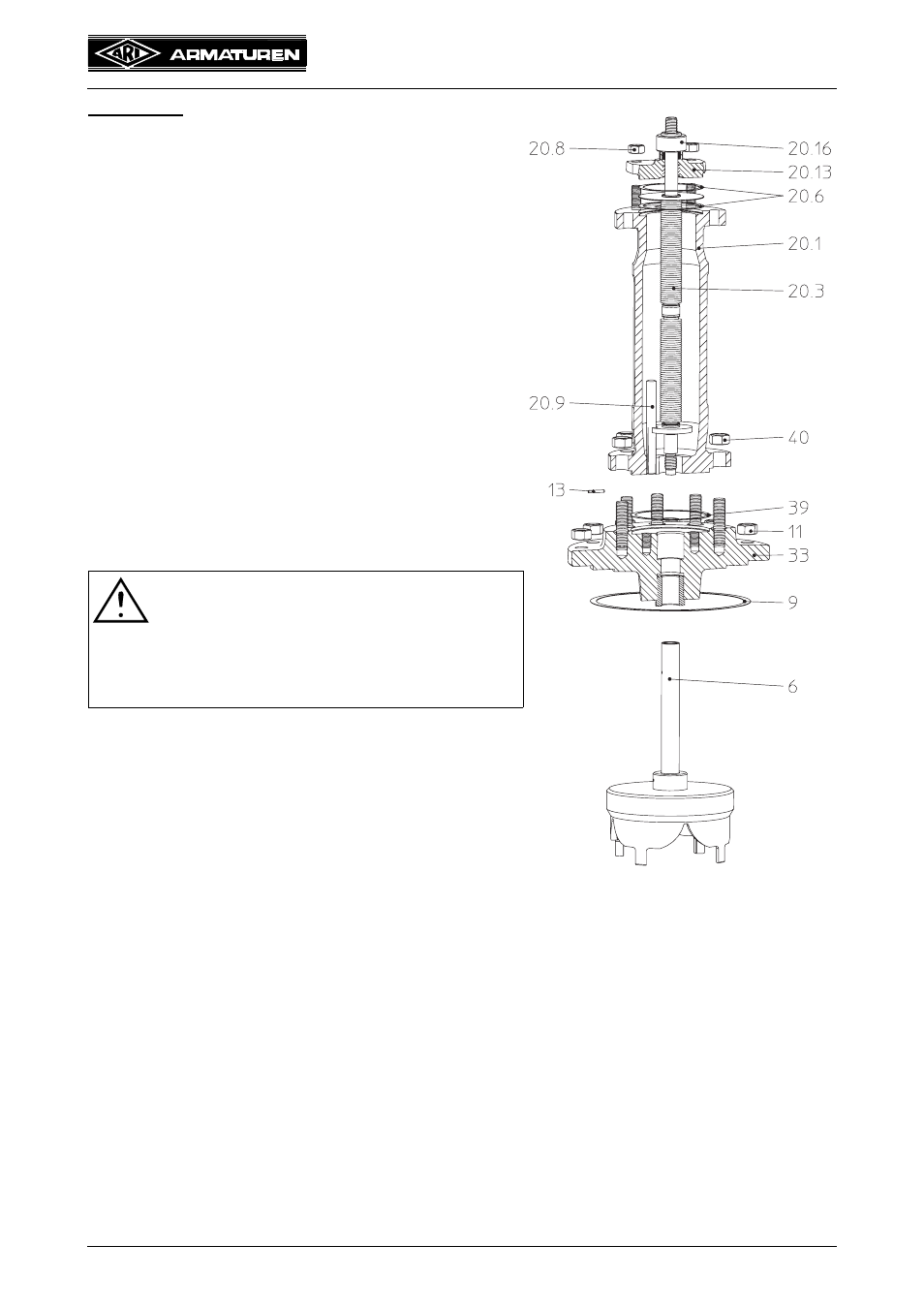
DN200-250:
- Loose nuts (pos. 11).
- Detach bellows assembly (pos. 20) incl. stuffing
box housing (pos. 33).
- Slacken sleeve nut (pos. 20.16) by about one turn.
- Loose nuts (pos. 40).
- Lift bellows housing (pos. 20.1)
- Drive spring pin (pos. 13) out with a drift.
- Unscrew stem extension (pos. 25) with plug.
- Loose nuts (pos. 20.8).
- Detach stuffing box housing (pos. 20.13)
- Extract stem/bellows-unit (pos. 20.3) from the
bellows housing (pos. 20.1).
- Bolt new parts together and drill them.
- Replace 2 gaskets (pos. 20.6), 1 gasket (pos. 9)
and 1 gasket (pos. 39).
- Assemble in reverse order.
- Secure with nuts (pos. 11, 20.8 and 40) and tighten
them crosswise.
(For tightening torques refer to item 7.3)
- Tighten sleeve nut (pos. 20.16) gradually up to
tightness of the stuffing box packing (pos. 20.10).
ATTENTION at DN125-150!
- Ensure that the torsion lock is correctly
positioned when inserting new stem/
bellows unit. Introduce the grooved pin
(pos. 20.9) into the torsion lock groove.
Make sure it runs smoothly!
Fig. 23: Series 441 DN200-250