3 diagram, 1 parts, Operating and installation instructions predu – ARI Armaturen PREDU 700 EN User Manual
Page 5
Rev. 0040701000 1714
Page 2-5
Operating and installation instructions
PREDU
®
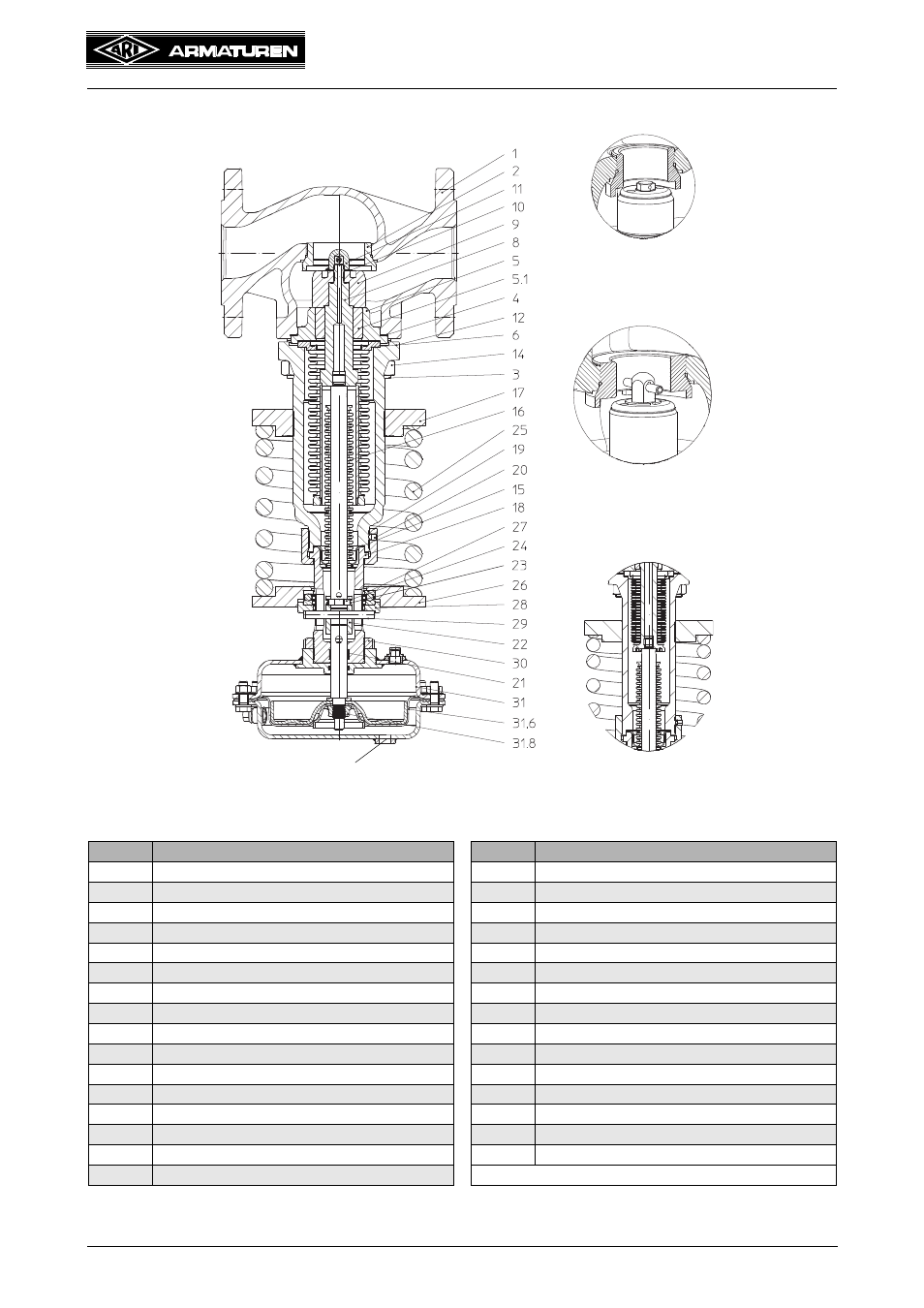
4.3 Diagram
4.3.1 Parts
Refer to the data sheet for information about materials with designations and figure
numbers.
Fig. 1
Pos.
Designation
Pos.
Designation
1
Body
19
Screw
2
Screwed seat
20
Thread pin
3
Stud
21
Guide bush
4
Gasket
22
Guide coupling
5
Bush housing
23
Cylindrical balls
5.1
Guide bush
24
Securing wire
6
Gasket
25
Spring
8
Balanced bellows unit
26
Spring plate
9
Plug unit
27
Axial bearing
11
Head
28
Pressure plate
12
Bonnet closed
29
Pin
14
Hexagon nut
30
Lock nut
15
Gasket
31
DMA-Pneumatic actuator
16
Sealing bellows unit
31.6
Rolling diaphragm
17
Adjusting plate
31.8
Collar nut
18
Head
Control line connection
Plug DN 15 - 32
Bellows DN 15 - 40
Plug DN 40 - 150
See also other documents in the category ARI Armaturen Equipment:
- STOBU PN 16 EN (13 pages)
- STOBU PN63-160 EN (18 pages)
- Metallic sealing EN (11 pages)
- FABA-Plus EN (15 pages)
- EURO-WEDI EN (10 pages)
- FA160 EN (17 pages)
- ASTRA DN15-80 EN (12 pages)
- ASTRA Plus DN15-80 EN (13 pages)
- CHECKO-D DN 125-350 EN (8 pages)
- CHECKO-V PN6-160 EN (12 pages)
- Strainer PN6-160 (10 pages)
- BR012-ZESA EN (15 pages)
- SAFE900 EN (18 pages)
- ARI REYCO R971 EN (18 pages)
- STEVI 405 DN 15-250 EN (18 pages)
- STEVI 405 DN 300-500 EN (16 pages)
- STEVI BBD 415 DN 25-50 EN (18 pages)
- STEVI 440 EN (21 pages)
- STEVI 450 EN (22 pages)
- STEVI 423 EN (16 pages)
- STEVI 423 DN300 EN (14 pages)
- STEVI 470 EN (1 page)
- STEVI 470 EN (16 pages)
- STEVI 422 EN (16 pages)
- STEVI 425 EN (16 pages)
- STEVI H 485 EN (14 pages)
- WA 306H EN (14 pages)
- CONA B PN16 EN (15 pages)
- CONA Universal ANSI 300 EN (17 pages)
- CONA all-in-one PN40 EN (18 pages)
- CONA M PN16 EN (12 pages)
- CONA M PN16 EN (13 pages)
- CONA S PN16 EN (9 pages)
- CONA S PN40 EN (15 pages)
- CONA S PN63 EN (18 pages)
- CONA S PN25 EN (11 pages)
- CONA S PN40 EN (13 pages)
- CONA SC PN16 EN (16 pages)
- CONA TD PN40 EN (13 pages)
- CODI S PN40 EN (13 pages)
- Condensate PN40 EN (14 pages)
- Liquid PN25 EN (11 pages)
- 0040807002 EN (2 pages)
- Steam injector PN25 EN (8 pages)