1 removing the hand wheel dn 15 - 150, 2 fitting the hand wheel and display dn 15 - 150, 2 mounting the hand wheel and display – ARI Armaturen ASTRA Plus DN250-400 EN User Manual
Page 7: In lagged pipe runs, Dn 15 - 150
Rev. 0040105005 0212
Page 7
Operating and installation instructions
ASTRA
®
Plus
- Planners / construction companies or operators are responsible for positioning and
installing products.
- The valves are designed for application, not influenced from weather.
- For application outside or in adverse environments like corrosion-promoting conditions
(sea water, chemical vapours, etc.), special constructions or protective measures are
recommended.
5.2 Mounting the hand wheel and display in lagged
pipe runs
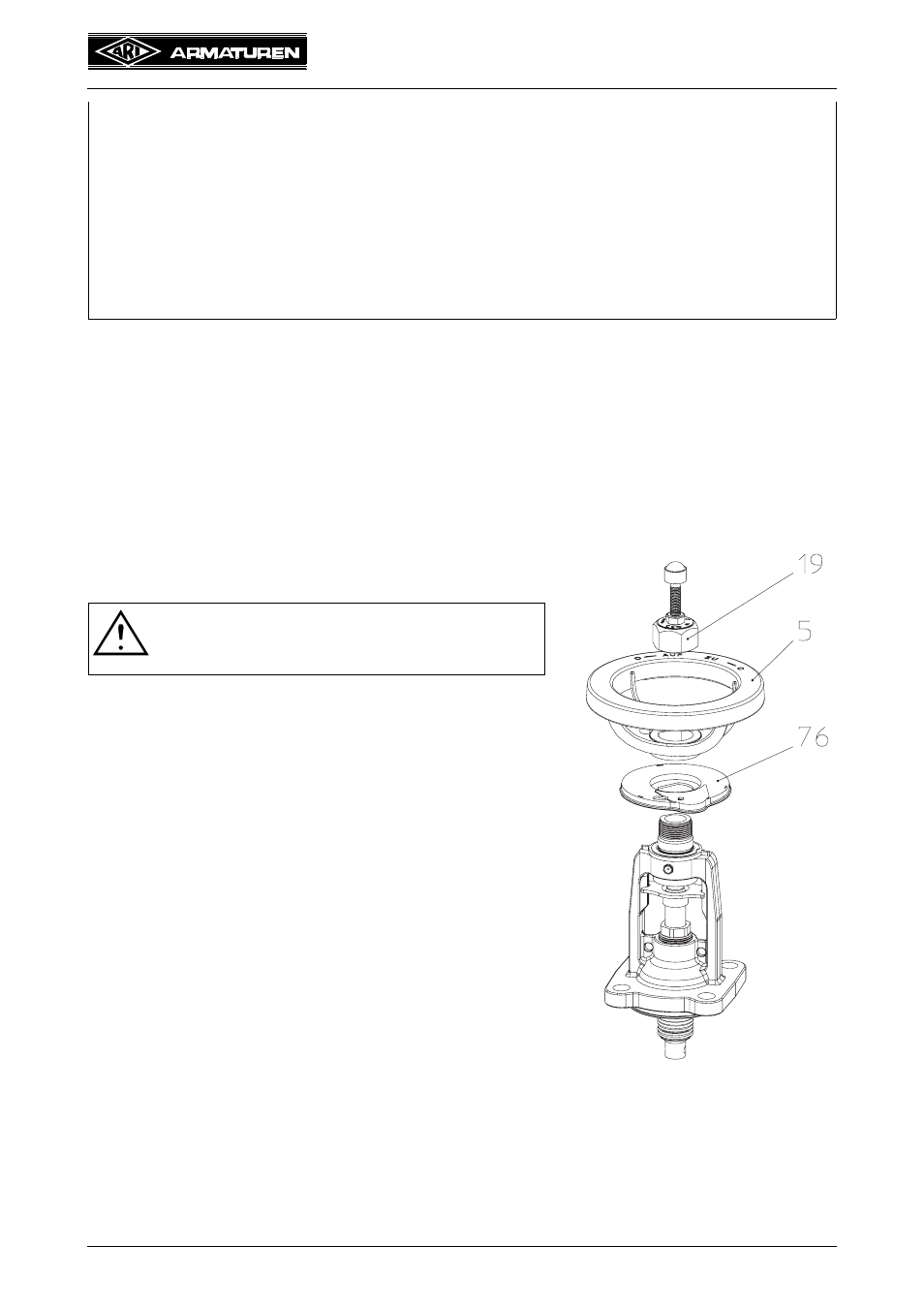
5.2.1 Removing the hand wheel DN 15 - 150
1. Close the valve by hand (pos. 5) (“0” position).
2. Unscrew the protection cap (pos. 19).
3. Lift off the hand wheel (pos. 5) and the digital display.
5.2.2 Fitting the hand wheel and display DN 15 - 150
1. Set the digital display (pos. 76) in place.
2. Set the hand wheel (pos. 5) in place.
3. Screw on the protection cap (pos. 19):
DN 15- 80 = 30 Nm
DN 100-200 = 40 Nm
- Valves can be installed with the spindle pointing in any direction, but the
prefered spindle position is vertical.
- Valves should be installed upside down only, if the medium being handled is
clean.
- Centre gaskets between the flanges.
- It is forbidden to heat the valve to above its service temperature (see data
sheets), for instance by welding, grinding, etc.
- To ensure that the valves function correctly, the pipe run should be straight for
at least 6 x DN upstream and 2 x DN downstream of the valve.
ATTENTION !
- The handwheel must be secured (hold tight)
when removing the protection cap
Fig. 6