Installing the rocketraid host adapter – HighPoint RocketRAID 2302 User Manual
Page 16
RocketRAID 230x Hardware Description/Installation
LED Connections – RR2304
The RocketRAID 2304 does not provide LED connectors. It was designed for use
with external drive enclosures, rather than internal disk configurations.
Note:
these LED connectors were designed for use with SATA and SATAII
backplanes (typically used in hot-swap enclosures or drive bays designed for use
with server chassis). They were not designed for use with standard 2-pin LED’s
(commonly used by desktop chassis).
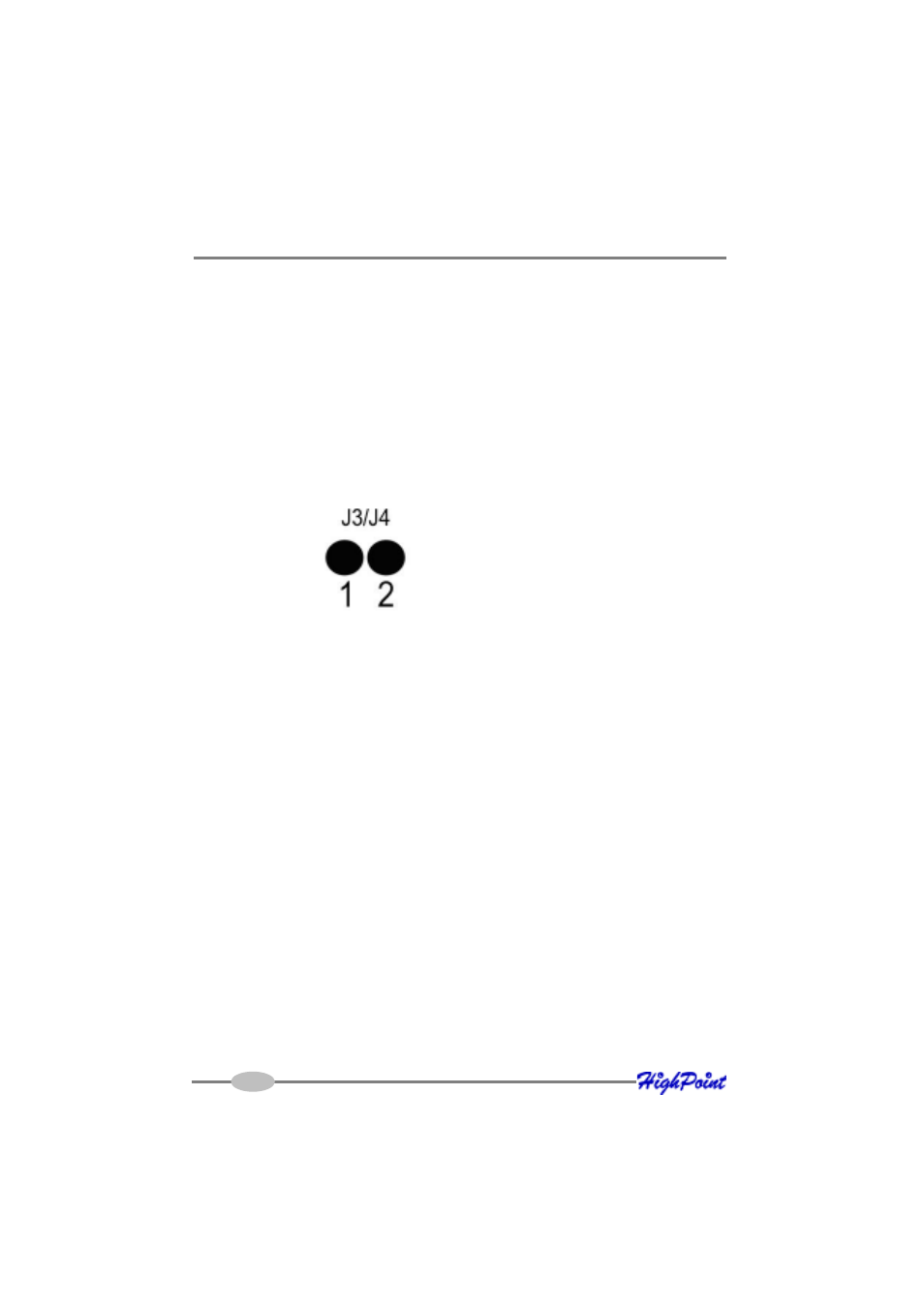
LED Connections – RR2302
The RocketRAID 2302 provides LED connectors for it’s two internal SATA channels.
Pins 1 and 2 represent SATA channel 1 and 2 respectively.
J3 provides LED support for Disk Failure, while J4 supports Disk Activity.
Note:
As with the RR2300 model, these LED connectors were designed for use with
SATA and SATAII backplanes (typically used in hot-swap enclosures or drive bays
designed for use with server chassis). They were not designed for use with standard
2-pin LED’s (commonly used by desktop chassis).
2-6
3- Installing the RocketRAID Host Adapter
Note: Make sure the system is powered-off before installing the RocketRAID host
adapter.
The RocketRAID 2300 and 2302 models include both standard and low-profile
brackets. It may be necessary to attach the low-profile bracket in place of the stan-
dard bracket, depending upon the chassis design. The RocketRAID 2304 is a full-
height card, and is not designed for use with low-profile chassis.