Asus AP2400R User Manual
Page 30
30
Chapter 3: Hardware Setup
DIMM Installation
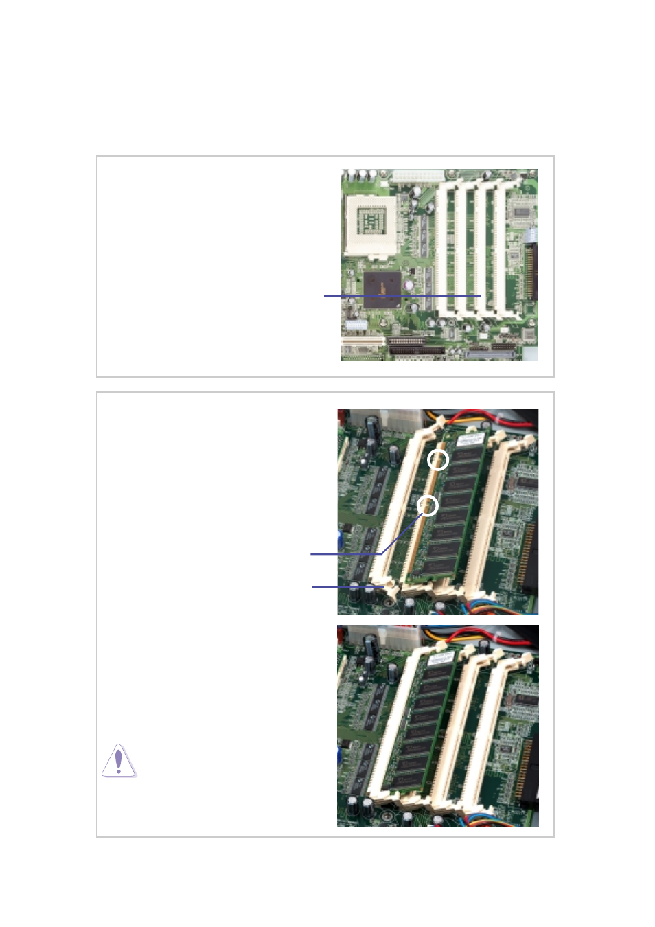
(1) Unlock a DIMM socket by pressing
the retaining clips outward. Align a
DIMM on the socket such that the
notches on the DIMM (indicated by
white circles on the figure) match the
breaks on the socket.
(2) Carefully insert the DIMM on the
socket until the retaining clips snap
back in place.
CAUTION:
DIMMs fit in only direction. DO
NOT force a DIMM into the
socket to avoid damaging the
DIMM.
DIMM Sockets Location
Locate the DIMM sockets on the
motherboard to install memory
modules.
4 DIMM Sockets
System Memor y
The motherboard has four Dual Inline Memory Module (DIMM) sockets
that support 3.3V Synchronous Dynamic Random Access Memory
(SDRAM) modules in 16, 32, 64, 128, 256, 512MB, or 1GB densities.
DIMM Socket Retaining Clip
DIMM Notches
- CG8565 (410 pages)
- CG8565 (246 pages)
- CS5111 (26 pages)
- CS5120 (1 page)
- ET1611PUK (38 pages)
- S2-P8H61E (80 pages)
- P2-PH1 (80 pages)
- P1-P5945G (80 pages)
- P2-P5945GCX (90 pages)
- CG8270 (218 pages)
- CG8270 (536 pages)
- CG8270 (72 pages)
- CG8270 (76 pages)
- CG8270 (534 pages)
- CG8270 (362 pages)
- P3-PH4 (80 pages)
- P3-P5G31 (100 pages)
- P2-M2A690G (80 pages)
- P2-M2A690G (8 pages)
- P4-P5N9300 (82 pages)
- P4-P5N9300 (1 page)
- P1-P5945GC (92 pages)
- P2-P5945GC (92 pages)
- P3-P5G33 (98 pages)
- T3-P5945GC (80 pages)
- T3-P5945GCX (80 pages)
- P2-M2A690G (94 pages)
- T3-PH1 (80 pages)
- T3-PH1 (82 pages)
- T5-P5G41E (82 pages)
- T5-P5G41E (76 pages)
- S1-AT5NM10E (68 pages)
- P6-P7H55E (67 pages)
- ES5000 (174 pages)
- T4-P5G43 (104 pages)
- T-P5G31 (92 pages)
- BT6130 (60 pages)
- BT6130 (54 pages)
- BT6130 (2 pages)
- CG8265 (210 pages)
- CG8265 (350 pages)
- CM1740 (330 pages)
- CM1740 (70 pages)
- CM1740 (198 pages)
- P6-M4A3000E (59 pages)