Calibration, 1 getting started – Vaisala Calibration of Series HMDW6070 and HMP140 Transmitter with HMI41 User Manual
Page 17
HMI41 Calibration Option
19116ZZ-U218en-1.1
Operating Manual
1996-08-29
13
3.
CALIBRATION
For a successful calibration, it is essential that the probe of the HMI41 and
that of the transmitter are at the same temperature, and that the reference
probe has been previously calibrated. Always allow enough time for the
readings to stabilize. Note that the stabilization time depends on the ambient
conditions and may vary from 10 minutes to a couple of hours.
3.1
Getting started
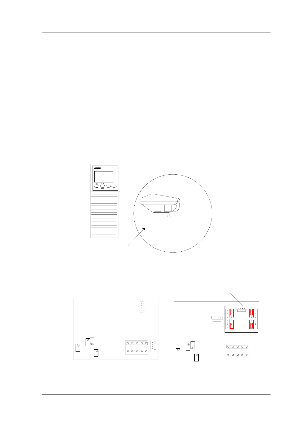
After having selected the desired function (Chapter 1.2) and necessary scale
selections (Chapter 2), turn the HMI41 off and connect the calibration cable to
the EXT connector at the bottom of the HMI41 (see Figure 3.1) and to the
appropriate connector in the transmitter (see Figures 3.2 - 3.4).
EN TER
MO DE
HOLD
ON/OFF
EXT
C o n n e c t o r f o r t h e
c a l i b r a t i o n c a b l e
Figure 3.1
Location of the HMI41 calibration connector
T GAIN
RH GAIN
RH OFFSET
T OFFSET
T
TEST
TEST
RH
HMD60U/Y
T GAIN
RH GAIN
RH OFFSET
T OFFSET
TEST CONNECTOR
U
U
U
U
I-module 0-20mA
1
1
TEST CONNECTOR
FOR CURRENT OUTPUTS
FOR VOLTAGE OUTPUTS
HMD70U/Y
Figure 3.2
Calibration connectors and potentiometers in
the HMD60 and HMD70 transmitters