Vaisala Calibration of Series HMDW6070 and HMP140 Transmitter with HMI41 User Manual
Page 12
HMI41 Calibration Option
Operating Manual
19116ZZ-U218en-1.1
8
1996-08-29
RH
set
Hi
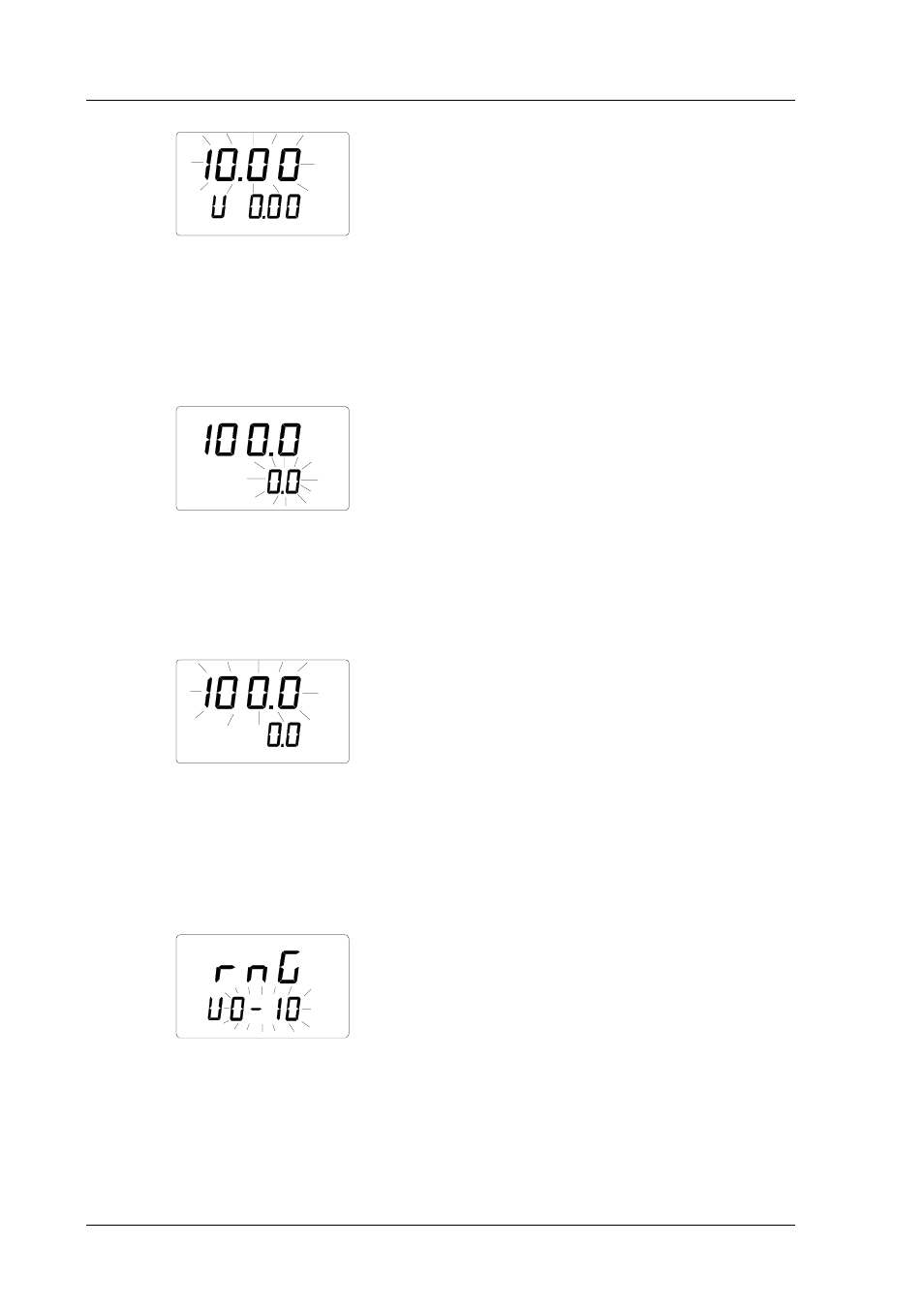
Numbers on the first line start to blink. They indicate the upper limit of the
transmitter’s voltage range currently stored in the HMI41 memory and the text
in the lower righthand corner is Hi. You can now set the upper limit of the
voltage range to correspond to that of the transmitter. Set the limit with
buttons ▲ or ▼ and acknowledge the setting with ENTER. A text similar to
the following is displayed:
RH
set
Lo
%
Numbers on the second line are blinking. They indicate the lower limit of the
transmitter’s RH range currently stored in the HMI41 memory. Text in the
lower righthand corner is Lo. You can now set the lower limit of the RH range
to correspond to that of the transmitter. Set the limit with buttons ▲ or ▼ and
acknowledge the setting with ENTER:
RH
set
Hi
%
Numbers on the first line start to blink. They indicate the upper limit of the
transmitter’s RH range currently stored in the HMI41 memory. Text in the
lower righthand corner is Hi. You can now set the upper limit of the RH range
to correspond to that of the transmitter. Set the limit with buttons ▲ or ▼ and
acknowledge the setting with ENTER. The HMI41 goes on to T channel
settings, and a text similar to the following is displayed:
T
set