1 humidity channel – Vaisala Calibration of Series HMDW6070 and HMP140 Transmitter with HMI41 User Manual
Page 11
HMI41 Calibration Option
19116ZZ-U218en-1.1
Operating Manual
1996-08-29
7
2.3.3.1
Humidity channel
RH
set
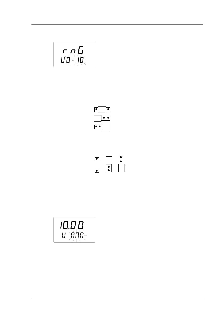
Numbers on the display are blinking. They indicate the voltage range of the
transmitter’s RH channel (jumper selectable) currently stored in the HMI41
memory. Please, consult Figures 2.3.1 - 2.3.2 when checking the transmitter’s
jumper positions.
RH output
selections
0...1V
0...5 V
0...10 V
Figure 2.3.1
Jumper selections of the HMD/W70
RH output
selections
0...1V
0...10 V
0...5 V
Figure 2.3.2
Jumper selections of the HMP140
Numbers on the second line are blinking, and you can now select the range
with buttons ▲ or ▼ according to the transmitter’s jumper position.
Acknowledge the selection with ENTER. A text similar to the following is
displayed:
RH
set
Lo
Numbers on the second line are blinking. They indicate the lower limit of the
transmitter’s voltage range currently stored in the HMI41 memory. Text in the
lower righthand corner is Lo. You can now set the lower limit of the voltage
range to correspond to that of the transmitter. Set the limit with buttons ▲ or
▼ and acknowledge the setting with ENTER: