Fire and explosion hazard – State SSX100 User Manual
Page 51
51
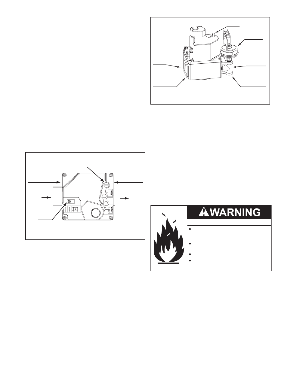
GAS VALVE SIDE VIEW
120,000 Btu/hr MODELS
MANIFOLD GAS
PRESSURE TAP
1/8’ NPT PLUG
SUPPLY GAS
PRESSURE TAP
1/8’ NPT PLUG
BOTTOM OF TEE
1/8” NPT
TEE FITTING
GAS VALVE
OUTLET
ON/OFF
SWITCH
LOW GAS
PRESSURE
SWITCH
figure 53
6. Compare the actual manifold gas pressure reading recorded
above to the required minimum/maximum values given
in Table 4 on page 13. Adjust manifold gas pressure as
necessary, see manifold Gas Pressure Adjustment on page 52.
7. record the supply gas pressure when the 24 Volt Gas Valve is
energized and the main burner is ignited. This is a “dynamic”
gas pressure reading; while the water heater is firing.
8. Compare the actual supply gas pressure reading recorded
above to the required minimum/maximum values given in
Table 4 on page 13. Adjust supply gas pressure as necessary,
see Supply Gas Pressure Adjustment on page 51.
9. When complete turn off gas to the water heater, see
instructions on page 53. Disconnect manometers and replace
all pipe plugs removed for testing. ensure all test port needle
valves opened during testing are completely closed.
suPPLy gAs PREssuRE AdjustMEnt
Fire and Explosion Hazard
Do not use water heater with any gas
other than the gas shown on the rating
label.
Excessive gas pressure to gas valve can
cause serious injury or death.
Turn off gas lines during installation.
Contact a qualified installer or service
agency for installation and service.
Supply gas pressure shall be measured while the water heater is
not firing (static pressure) AND while the water heater is firing at
full capacity (dynamic pressure).
If the supply gas pressure to the water heater is not between the
required minimum and maximum values given in Table 4 on page
13 adjust the supply gas regulator as necessary. Adjust the supply
gas regulator(s) per the regulator manufacturer’s instructions to
achieve the required “static” and “dynamic” supply gas pressure.
6. Connect one manometer (lower range) to an available test
port for manifold gas pressure to the main burner:
SSF/SSX 100 models: remove the 1/8 inch pipe plug from
the body of the gas valve on the outlet side and install a barb
fitting to connect the manometer sensing tube, see Figure 52
on page 51.
7. open the main Gas Shutoff Valve.
8. measure and record the supply gas pressure, this is a “static”
supply gas pressure reading; while the water heater is not
firing. Adjust supply gas pressure as necessary, see Supply
Gas Pressure Adjustment on page 51.
LIghtIng thE wAtER hEAtER
1. SSF/SSX 100 models: turn the on/off switch on the gas valve
to the "on" position, see Figure 52 and Figure 53.
2. Turn the water heater’s on/off switch to the “on” position.
3. Wait for the control system to complete its boot up sequence.
The Desktop screen showing the current operating Set
Point and Tank Temperature will be displayed on the control
system’s lCD when the boot up sequence is complete.
4. using the control system menus and uIm (user interface
module), change the operating Set Point to a setting higher
than the current tank temperature displayed on the control
system lCD plus the Differential setting to activate a call for
heating. See Control System operation on page 42.
ON
OFF
MANIFOLD GAS
PRESSURE REGULATOR
COVER SCREW
GAS VALVE TOP VIEW
120,000 Btu/hr MODELS
MANIFOLD GAS
PRESSURE TAP
1/8’ NPT PLUG
SUPPLY GAS
PRESSURE TAP
1/8’ NPT PLUG
INLET
OUTLET
ON/OFF
SWITCH
figure 52
5. record the manifold gas pressure when the 24 Volt Gas Valve
is energized and the main burner is ignited, the animated gas
valve icon will be displayed on the Desktop screen of the
control system’s lCD when the control system energizes the
24 Volt Gas Valve, a animated flame icon will appear when
main burner ignition is successful, see the Status Icons
descriptions in Table 11 on page 43.