Reference parts listing – State GS6 75 YRDS L User Manual
Page 40
40 www.
statewaterheaters.com
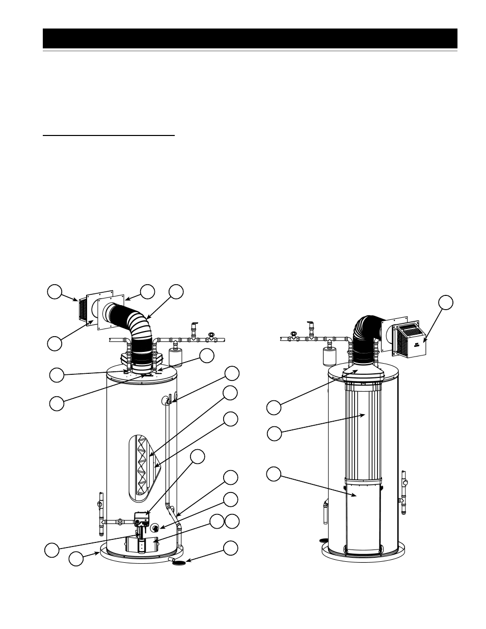
REFERENCE PARTS LISTING
Replacement parts may be ordered
through your plumber or the local
distributor. When ordering replacement
parts, always have the following
information ready:
1. Model, Serial and Product number
2. Type of gas
3. Item
number
4. Parts
description
1 Vent Termination Hood
2 Wall Plate
3 ***Vent Pipe
4 Cold Water Inlet Nipple/Diptube
6 T&P Valve
7 Gas Control Valve/Thermostat
(Honeywell)
9 *Discharge Pipe
10 Drain Valve
11 Outer Gas Door
12 Manifold Door Assembly (behind
outer door) (see Figure 3 &
Figure 4) (see also Figure 47 &
Figure 48
)
13 *Floor Drain
14 *Metal Drain Pan
15 Flexible Manifold Tube (see
Figure 3 & Figure 4) (see also
Figure 47 & Figure 48)
22 Anode (under cap)
23 Hot Water Outlet Nipple (or Optional
Nipple/Anode)
26 Air Inlet Snorkel
27 Air Tower
28 ***Airbox
29 *Thermal Expansion Tank (required
for all closed systems)
30 Sheet Metal Burner (see Figure 3 &
Figure 4) (see see also Figure 47 &
Figure 48)
31 Gas Orifi ce (see Figure 3 &
Figure 4) (see also Figure 47 &
Figure 48)
32 Gas Manifold (see Figure 3 & Figure
4) (see also Figure 47 & Figure 48)
33 Manifold Door Gasket (see Figure 3 &
Figure 4) (see also
Figure 47 & Figure 48)
34 Manifold Door (see Figure 3 & Figure
4) (see also Figure 47 & Figure 48)
35 Two Piece Grommet With Clip (see
Figure 3 & Figure 4) (see also
Figure 47 & Figure 48
)
36 Viewport (see Figure 3 & Figure 4)
(see also Figure 47 & Figure 48)
37 Flexible Manifold Tube (see
Figure 3 & Figure 4) (see also
Figure 47 & Figure 48
)
38 Pilot (see Figure 3 & Figure 4) (see
also Figure 47 & Figure 48)
39 Thermopile (see Figure 3 &
Figure 4) (see also Figure 47 &
Figure 48
)
40 Pilot Shield (see Figure 3 &
Figure 4) (see also Figure 47 &
Figure 48
)
* Items not supplied with the water
heater.
*** During operation the vent pipe and
airbox can get hot.
23
1
3
2
6
4
9
10
13
14
15
2
11 12
4
7
22
22
Front View
Figure 45
Figure 46
26
1
27
28
Rear View