Warning, Figure 15, Breathing hazard - carbon monoxide gas – State GS6 75 YRDS L User Manual
Page 22
22 www.
statewaterheaters.com
VENTING
This direct vent water heater uses a sealed venting
system to supply fresh combustion air to the heater and
to exhaust the products of combustion (fl ue gases) to the
outdoors. The venting is a “pipe in a pipe” system. The
inner (3”) piping carries out the exhaust fl ue gases while
the outer (6”) piping carries in fresh combustion air. The
corrugated end of the vent piping connects to the top of
the water heater and the opposite end connects to the vent
termination hood which will be mounted on the exterior wall
(see Figure 16). Figure 16 shows the hot exhaust gas exit
and the location of the combustion air intake.
Figure 19 thru Figure 26 show how to assemble and
connect the venting system.
Figure 28 thru Figure 30 show various installation options.
DO NOT STORE OR USE GASOLINE OR OTHER
FLAMMABLE VAPO RS AND LIQUIDS IN THE VICINITY
OF THE VENT TERMINATION HOOD.
NEVER OPERATE THE WATER HEATER UNLESS IT IS
VENTED TO THE OUTDOORS AND HAS ADEQUATE AIR
SUPPLY TO AVOID RISKS OF IMPROPER OPERATION,
FIRE, EXPLOSION OR ASPHYXIATION.
DO NOT OBSTRUCT THE FLOW OF COMBUSTION AND
VENTILATING AIR. ADEQUATE AIR FOR COMBUSTION
AND VENTILATION MUST BE PROVIDED FOR SAFE
OPERATION.
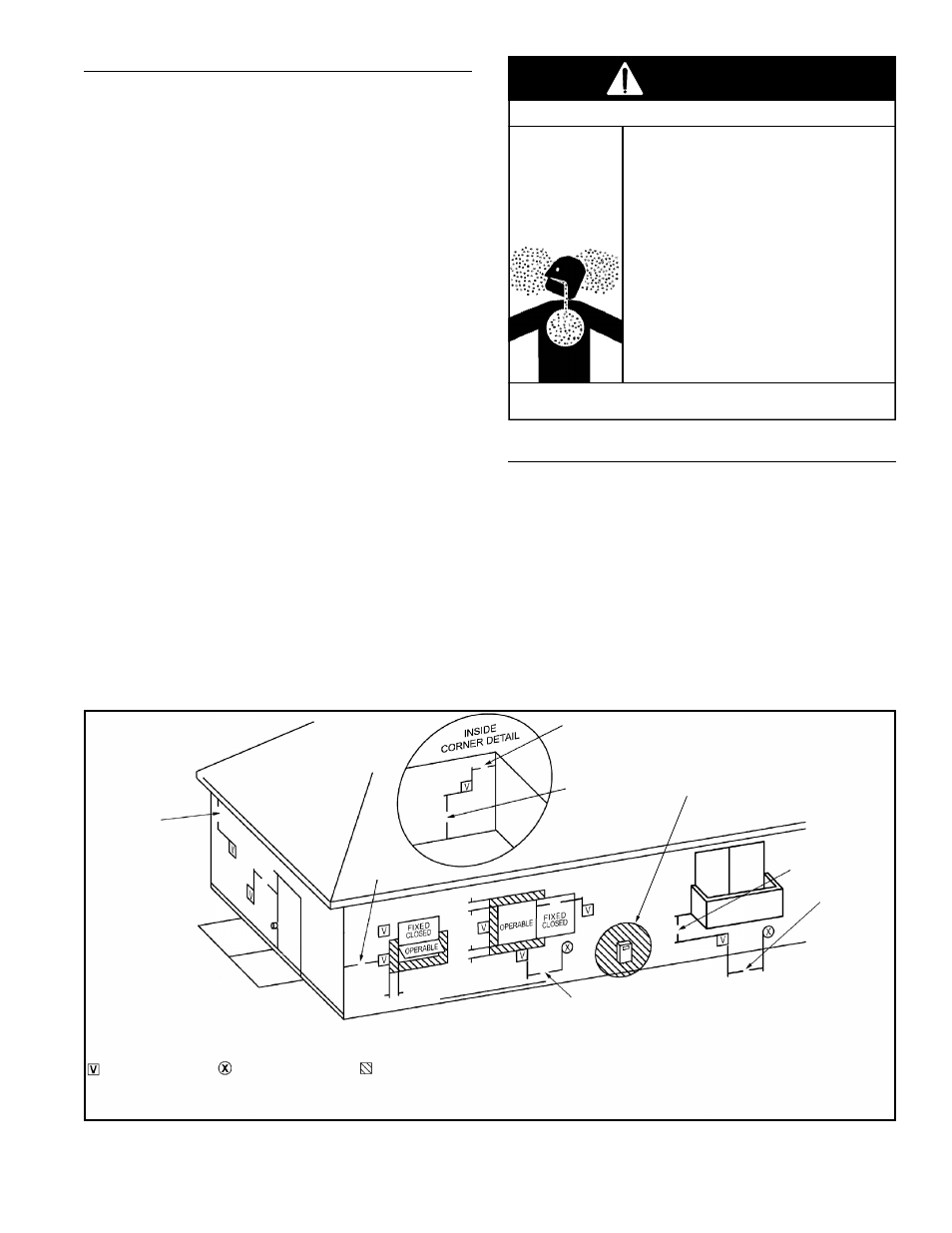
**Minimum 12 in.
Minimum 12 in.
above grade or
anticipated snow
level
Minimum 12 in.
under veranda, porch,
deck or balcony
(see footnote 1)
Minimum
3 ft.
above if within
10 ft.
horizontally to
a mechanical air
supply inlet
Minimum 9 in. to a non mechanical air supply inlet
into building or combustion air inlet to another appliance
Minimum 12 in.
from soffit
*Minimum 9 in. to
a window or door
that may be opened
**Minimum
18 in.
from outside
corner
1. Permitted only if veranda, porch, deck or balcony is fully opened on a minimum of two sides beneath the floor.
2. A vent shall not terminate above a sidewalk or paved driveway that is located between two single family dwellings and serves both dwellings.
AREA WHERE TERMINAL IS NOT PERMITTED
VENT TERMINAL
AIR SUPPLY INLET
Minimum
3 ft.
clearance to a
service regulator
vent outlet
** Or as required by local authorities.
Figure 15
Breathing carbon monoxide can cause brain damage or death.
Always read and understand instruction manual.
• Install vent system In accordance with codes.
• Do not operate water heater if flood damaged.
• Install water heater in accordance with the
instruction manual.
• Do not operate if soot buildup is present.
• Do not obstruct water heater air intake.
• Do not place chemical vapor emitting products near
water heater or vent terminal hood.
• Gas and carbon monoxide detectors are available.
• Never operate the heater unless it is vented to the
outdoors and has adequate air supply to avoid risks
of improper operation, fire, explosion or asphyxia-
tion.
• Analyze the entire vent system to make sure that
condensate will not become trapped in a section of
vent pipe and therefore reduce the open cross
sectional area of the vent.
• Chemical corrosion of flue and vent system can
cause serious injury or death.
Breathing Hazard - Carbon Monoxide Gas
WARNING
VENT TERMINAL CLEARANCES
The vent system must terminate so that proper clearances
are maintained as cited in local codes or the current edition
of the “National Fuel Gas Code”, ANSI Z223.1/NFPA
54 as follows: