State GS6 75 YRDS L User Manual
Page 33
www.
statewaterheaters.com 33
BURNER FLAMES
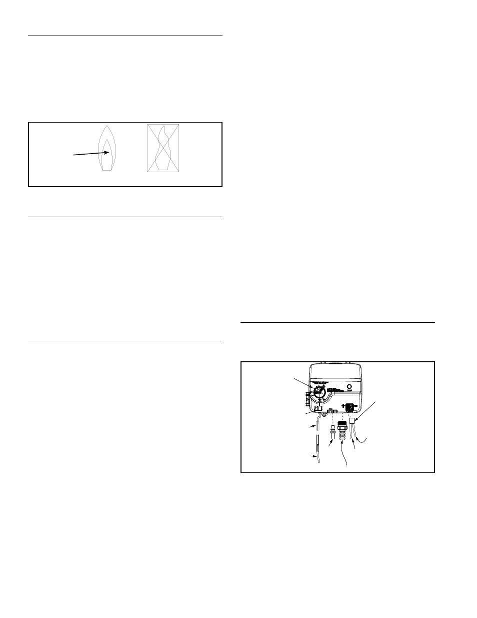
Inspect the burner flames through the viewport and
compare them to the drawings in Figure 32. A properly
operating burner should produce a soft blue fl ame. Blue
tips with yellow inner cones are satisfactory. The tips of the
fl ame may have a slight yellow tint. The fl ame should not be
all yellow or have a sharp blue-orange colo r. Contaminated
air may cause an orange colo red fl ame. Contact a qualifi ed
service technician if the fl ame is not satisfactory
CORRECT FLAME
SOFT BLUE
INCORRECT
FLAME LAZY
YELLOW
TIPS MAY HAVE
A YELLOW TINT
YELLOW INNER
CONES ARE
SATISFACTORY
Figure 32
SERVICING THE WATER HEATER
Servicing this water heater shall be done by qualifi ed
service personnel only.
1. Before performing any maintenance, it is important
to turn “OFF” the gas supply to the water heater at
the manual gas shut-off valve. This valve is typically
located beside the water heater. Note the position of
the shut-off valve in the open/on position, then proceed
to turn it “OFF” (see Figure 1).
2. With the water heater shut-off, allow suffi cient time for
the it to cool off before performing any service.
REMOVING AND REPLACING THE GAS CONTROL
VALVE/THERMOSTAT
Removing The Gas Control Valve/Thermostat:
1. Turn the gas control/temperature knob to the “OFF”
position (see Figure 31 and Figure 33).
2. Turn “OFF” the gas at the manual gas shut-off valve
(see Figure 1).
3. Drain the water heater. Refer to the “Draining, Refi lling
And Flushing” section and follow the procedure.
4. Disconnect the igniter wire from the igniter lead wire.
Use needle nose pliers to disconnect the thermopile
connector. Disconnect the pilot tube (7/16” wrench)
and manifold tube (3/4” wrench) at the gas control
valve/thermostat (see Figure 33).
Note: Propane (LP) Gas systems use reverse (left-hand)
threads on the manifold tube.
5. Refer to “Gas Piping” and disconnect the ground joint
union in the gas piping (see Figure 13 & Figure 14).
Disconnect the remaining pipe from the gas control
valve/thermostat.
6. To remove the gas control valve/thermostat, thread a
4” section of gas pipe into the inlet and use it to turn
the gas control valve/thermostat (counterclockwise).
Do not use a pipe wrench or equivalent to grip body.
Damage may result, causing leaks. Do not insert
any sharp objects into the inlet or outlet connections.
Damage to the gas control valve/thermostat may
result.
Replacing The Gas Control Valve/Thermostat:
To replace the gas control valve/thermostat, reassemble
in reverse order. When replacing the gas control valve/
thermostat, thread a 4” section of gas pipe into the inlet and
use it to turn the gas control valve/thermostat (clockwise).
DO NOT OVER TIGHTEN; damage may result.
•
Be sure to use approved Tefl on
®
tape or pipe joint
compound on the gas piping connections and fi tting
on the back of the gas control valve that screws into
the tank.
•
Be sure to remove the pilot ferrule nut from the new gas
control valve/thermostat. Reconnect the manifold tube,
pilot tube, igniter wire and the thermopile connections.
•
Turn the main gas supply “ON” and check the gas
supply connections for leaks. Correct any leak found.
•
Light the pilot and main burner, then check the manifold
tube and pilot tube connections for leaks. Use an
approved noncorrosive leak detection solution. If such
a solution is not available, use a mixture of hand dish
washing soap and water (one part soap to 15 parts
water) or childrens’ soap bubble solution. Bubbles
forming indicate a leak. Correct any leak found.
•
Be sure tank is completely fi lled with water before
lighting and activating the water heater. Follow the
lighting instructions on the label or see “Lighting
Instructions” to restart the water heater.
If additional information is required, reference the number
on the cover of this manual for service information.
TEFLON
®
is a registered trademark of E.I. Du Pont De Nemours and
Company
REMOVING THE MANIFOLD/BURNER ASSEMBLY
1. Turn the gas control/temperature knob to the “OFF”
position (see Figure 31 and Figure 33).
2. Turn “OFF” the gas at the manual gas shut-off valve
(see Figure 1).
IGNITER
WIRE
RED WIRE
PILOT
TUBE
MANIFOLD TUBE
IGNITER
BUTTON
IGNITER
LEAD
WIRE
WHITE
WIRE
GAS CONTROL/
TEMPERATURE
KNOB
THERMOPILE
CONNECTOR
Figure 33
3. Remove the outer door.
4. Disconnect the following from the gas control valve/
thermostat: pilot tube (7/16” wrench), igniter wire (from
the igniter lead wire), and manifold tube (3/4” wrench)
(see Figure 33).
Note: Propane (LP) Gas systems use reverse (left-hand)
threads on the manifold tube.
5. Use needle nose pliers to disconnect the thermopile
connector from the gas control valve/thermostat (see
Figure 33).
6. Grasp the manifold tube and push down slightly to