State GS6 75 YRDS L User Manual
Page 26
26 www.
statewaterheaters.com
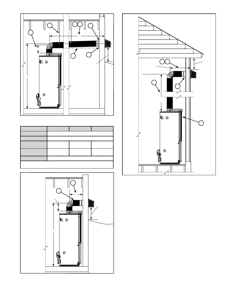
ABOVE
ANTICIPATED
SNOW
LEVEL OR
12” ABOVE
GRADE
A
B
Low Vent installation
7
6
8
1
C
5
1
9
Figure 28
DIM.
4038
5040
5047
A
80” MAX.
B
9” MIN.
C
(RECOMMENDED)
63.63”
73.00”
74.00”
C
(MINIMUM)
60.75
69.50
70.50
D
14.25” MIN.
NOTE: Dimension “C” is the height above to fl oor to the center of the
termination hole through the exterior wall.
D
4
Minimum Vent installation
C
ABOVE
ANTICIPATED
SNOW
LEVEL OR
12” ABOVE
GRADE
3
9”
Figure 29
12” MIN.
BELOW
SOFFIT
72”
MAX.
6
2
High Vent installation
5
1
1
17”
MIN.
Figure 30
NOTES: (applies to Figure 28 thru Figure 30)
1. In any installation the total of dimension “A” plus
dimension “B” must not exceed 89” .
2. This heater can be installed with 0” clearance to a wall.
3. Minimum vent pipe clearance to combustibles is 1”
(see Figure 21).
4. Minimum distance from center of heater to wall is
14.25” .
5. Dimension “A” includes wall thickness.
6. Hole diameter in wall is 7” .
7. Venting must slope up away from the heater a
minimum of 0.25” per foot of length to prevent
condensation from collecting and to provide
suffi cient draft.
8. Distance above horizontal at full extension is 2” .
9. Use support stays to hold the venting to avoid sags
or valleys.