State GS6 75 YRDS L User Manual
Page 25
www.
statewaterheaters.com 25
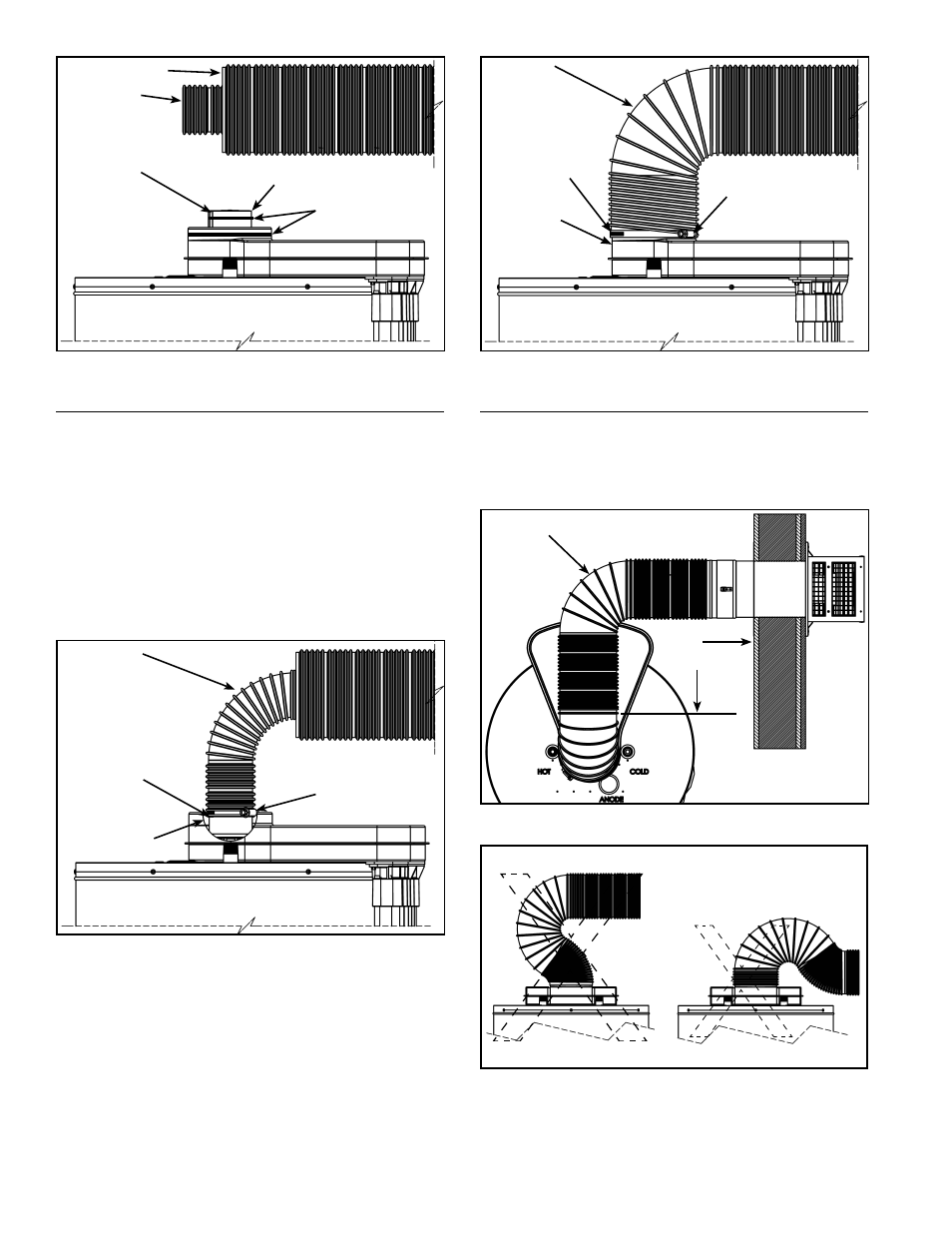
INNER
CORRUGATED
PIPE
OUTER
CORRUGATED PIPE
RESTRICTER
PLATE
FLUE TUBE
REDUCER
APPLY
SILICONE
Figure 23
VENT CONNECTION TO THE WATER HEATER
Bend both the corrugated pipes toward the fl ue connection
on the water heater. Pull and connect the inner corrugated
pipe to the water heater’s fl ue tube reducer with hi-temp
red silicone (included) and gear clamp. Make sure this
connection is tight and leak proof (see Figure 24).
*The sealant between the inner corrugated pipe and water
heater’s fl ue tube reducer must be hi-temp red silicone
or other material suitable for 600°F continuous service.
Note: If you are using the vent restricter plate, the inner
vent pipe is to go over the side legs and down the stops.
SMOOTH,
EASY CURVE
GEAR
CLAMP
CUTAWAY TO
SHOW DETAILS
RESTRICTER
PLATE STOP
Figure 24
Apply hi-temp red silicone (included) around the collar on
air manifold box. Pull the outer corrugated pipe all the way
on to collar and secure with the gear clamp. Pull the free
end of the corrugated pipe past the gear clamp and secure
with one sheet metal screw (see Figure 25).
GEAR
CLAMP
APPLY
SILICONE
TO AIRBOX
BEFORE
ATTACHING
PIPING
SECURE
WITH A
SHEET METAL
SCREW
SMOOTH,
EASY CURVE
Figure 25
OFFSET VENT ARRANGEMENT
Where a straight vent arrangement is impossible, a
horizontal 90° maximum bend can be made. Use the
water heater casing outer diameter as a template to form
the corrugated tube.
SMOOTH,
EASY CURVE
90°
MAXIMUM
BEND
Figure 26
Figure 27
Note: To ensure good exhaust gas fl ow, bend vent piping
using a smooth, easy curve as shown in Figure 24 thru
Figure 26. Do not use reverse or compound curves as
shown in Figure 27.