Definition of data stream items for the flexmax cc, Flexmax charge controller data stream – Outback Power Systems MATE3 USB Card Owner’s Manual User Manual
Page 16
FLEXmax Charge Controller Data Stream
14
900-0137-01-00 Rev
A
Definition of Data Stream Items for the FLEXmax CC
Port Number: Indicates the designation of the OutBack HUB port used by the charge controller. The addresses
will be 01 to 10 and will correspond to the appropriate numbered port. If the MATE3 is connected directly to the
charge controller without a HUB, this item will read 00.
Device Type: Indicates the presence of an OutBack charge controller of any model. This device type is always 3.
Charger Current: Measures the DC current delivered from the charge controller’s output to the batteries. The
range is 00 to 99 in increments of 1 ampere. (A separate item measures tenths of an amp. The MX60 controller
does not use this item.)
PV Current: Measures the DC current delivered from the PV array to the charge controller’s input. The range is
00 to 99 in increments of 1 ampere.
PV Input Voltage: The DC voltage as measured at the charge controller’s
input (PV) terminals. The range is 000 to 255 in increments of 1 volt.
Daily Kilowatt-Hours: The kilowatt-hours harvested by the charge
controller that day. The range is 000 to 999, incorporating one decimal
place. For example, a harvest of 55.5 kilowatt-hours will be sent as ‘555’.
This number is reset to zero any time the controller undergoes its wakeup
procedure, or every 24 hours.
AUX Modes: The current operating mode for the charge controller’s auxiliary
terminals. (See Table 16.) The range is 00 to 99. (The MX60 controller only
uses the first six modes on the list.) When the AUX output becomes active,
the 7
th
bit in each byte is set, adding 64 to the value. Hence, values below 63
indicate the selected AUX mode, while values above 63 also show
that it is active.
Fault Codes: This is an ASCII expression of an 8-bit binary string,
displayed in values ranging from 000 to 255. Each bit represents a
different fault as shown in Table 16. For example, a shorted battery
sensor would return an ASCII value of 32 (a binary value of
00100000). Only certain bits are used. (In MX60 controllers, this is
only valid with firmware above revision 5.11.)
Charger Mode: Reports the charge controller’s present status in a three-stage
charge cycle. The range is 00 to 99, although not all items are in use. Items
and their corresponding modes are shown in Table 17.
Silent: The controller has entered the quiescent period following a charging cycle.
Float: The controller is in a low constant-voltage charge, the last stage of a
charging cycle.
Bulk: The controller is in a constant-current charge, the beginning stage of a
charging cycle.
Absorb: The controller is in a high constant-voltage charge, the middle stage of a charging cycle.
Equalize: The controller is running equalization, a controlled overcharge for battery maintenance.
Battery Voltage: The DC voltage as measured at the charge controller’s battery terminals. The range is 000 to
999, incorporating one decimal place. For example, a 24.8 Vdc battery voltage will be sent as ‘248’.
Daily AH: The daily total of amp-hours delivered to the batteries by the charge controller. Range is 0000 to
2000. The number is reset to zero at midnight. This item is not valid for the MX60 controller; ‘9999’ will be
returned.
Checksum: This is a simple additive checksum of the decimal values of the Status page. Range is 000 to 999.
EXAMPLE:
00,3,00,08,06,034,031,00,05,000,02,262,000,000,045
0+0+3+0+0+0+8+0+6+0+3+4+0+3+1+0+0+0+5+0+0+0+0+2+2+6+2+0+0+0+0+0+0=045
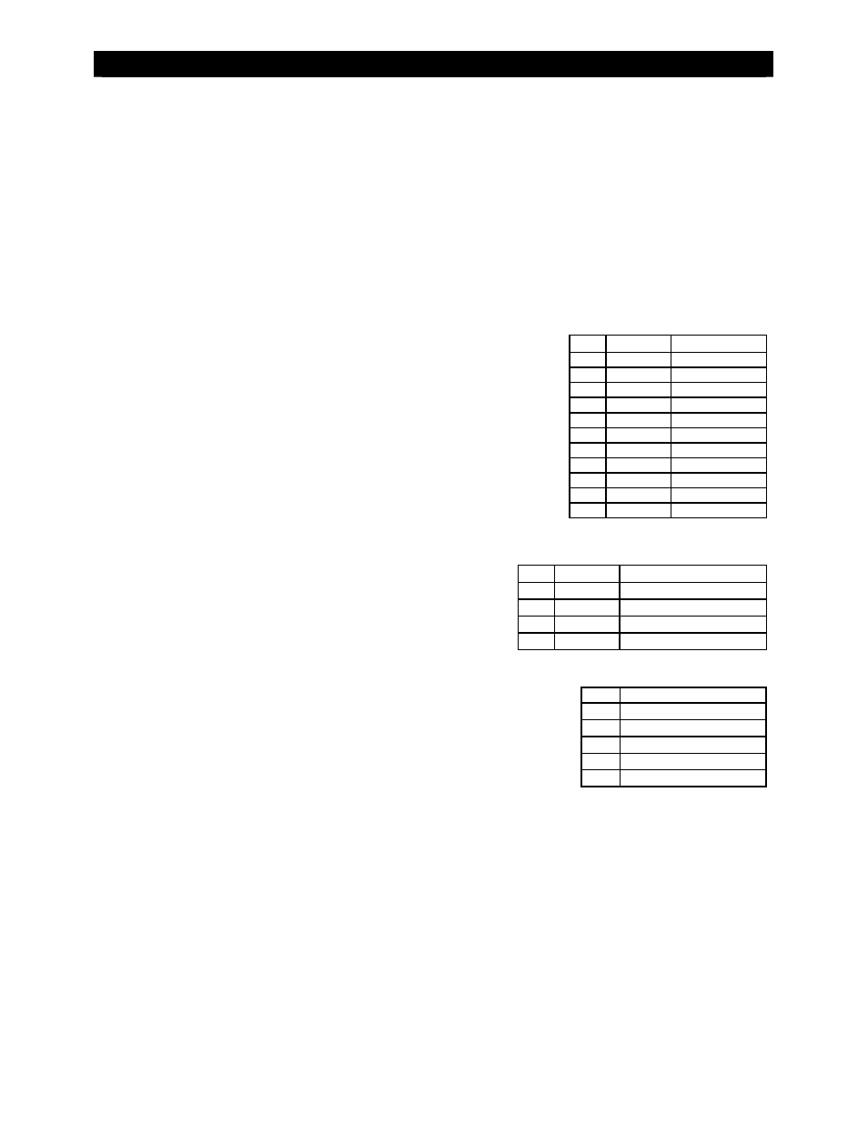
Table 15 CC AUX Modes
Data With Bit 7
Mode
00 64
Disabled
01 65
Diversion
02 66
Remote
03 67
Manual
04 68
Vent
Fan
05 69
PV
Trigger
06 70
Float
07 71 Fault
Output
08 72 Night
Light
09 73 PWM
Diversion
10 74 Low
Battery
Table 16 CC Fault Codes
Bit Value
Warning
1-5 1-16
unused
6 32 Shorted
battery
sensor
7 64
Too
hot
8 128
High
VOC
Table 17 CC Charger Modes
Data Mode
00 Silent
01 Float
02 Bulk
03 Absorb
04 Equalize