Bypass assembly, Installation – Outback Power Systems GS Load Center Installation Manual User Manual
Page 42
Installation
40
Bypass Assembly
Bypass switching can be used when the inverter is shut down for maintenance. This topic is discussed
more beginning on page 42. The GSLC can be equipped with the GS-IOB-230VAC bypass assembly.
The instructions on this page are for making external connections to the bypass assembly after
installation. (The installation wiring for the GS-IOB-230VAC is described on page 42.)
If the GSLC has no bypass assembly, connections should be made directly to each TBB from the circuit
breakers for the inverter, AC sources, and loads. These connections are designated in Figure 35.
Wiring diagrams for an assembled 230 Vac system are shown beginning on page 48.
Figure 36
Inverter AC Connections (single-phase)
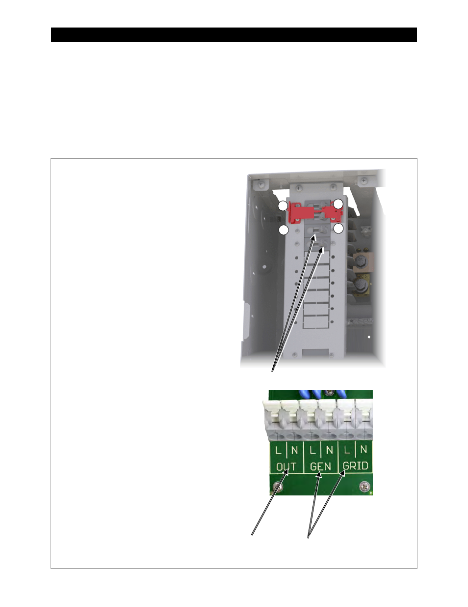
To make the connections to the
Radian inverter:
1. Designate the topmost AC circuit breaker
as the inverter AC output disconnect.
Install a wire from the AC output circuit TBB
(as shown in Figure 35) to that disconnect
as marked by
1
.
2. Install a wire on the left side of the
disconnect as marked by
2
. Connect the
wire to the appropriate output terminals on
the Radian inverter.
3. Designate the third AC circuit breaker as
the disconnect for one AC source (
GRID or
GEN). Install a wire from the TBB of the
appropriate source circuit (as shown in
Figure 35) to the left side of that disconnect
as marked by
3
.
4. Install a wire on the right side of the source
disconnect as marked by
4
. Connect the
wire to the appropriate input terminal on
the Radian inverter (the terminal labeled
either
GRID or GEN).
5. If a second AC source is present, repeat
steps 3 and 4.
6. Install a wire on the inverter’s
NEU terminal
and connect it to the GSLC’s neutral TBB
(as shown in Figure 35). Only one neutral
connection is required.
GRID and GEN inputs
AC output
Disconnects
2
4
1
3