Wiring, Grounding, E 29 – Outback Power Systems GS Load Center Installation Manual User Manual
Page 31: Ge 29
Wiring
29
Wiring
Table 2 Terminal Bus Bar (TBB) Wire Size and Torque Requirements
Conductor Size
Torque Requirements
AWG
mm²
In-lb
Nm
#14 – #10
2.5 – 4
20
2.3
#8
6 – 10
25
2.8
#6– #3
16 – 25
35
4.0
#2
35
40
4.5
#1 – 1/0
50
50
5.7
Grounding
WARNING: Shock Hazard
The unit must be connected to a permanent wiring system that is grounded
according to the IEC 60364 TN standard.
Make sure that no more than one bond is present in the AC system at any time.
Some codes require the bond to be made at the main panel only.
For safety, the neutral and ground conductors should be mechanically bonded.
The GS Load Center (GSLC) is equipped with a neutral-ground bond. If bonding is
required to be in another location, the bond in the GSLC may need to be removed.
Some generators have a neutral-ground bond. When establishing a single bond
elsewhere, it may be necessary to check for a generator bond.
WARNING: Shock Hazard
For all installations, the negative (–) battery conductor should be bonded to the
grounding system at only one point.
The GSLC comes equipped with a negative-
ground bond. This bond may need to be disconnected. If the OutBack GFDI is present, it
can provide the bond. See page 30.
IMPORTANT:
Most OutBack products are not designed for use in a positive-grounded system. If it is
necessary to build a positive-grounded system with OutBack products, contact OutBack
Technical Support at
+1.360.618.4363 before proceeding. Additionally, consult the
online forum a
here this subject has been
discussed extensively.
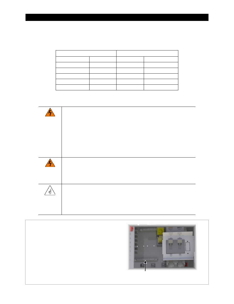
Figure 26
Grounding
The GSLC’s grounding terminal bus bar ( TBB), which is
bonded to the GSLC chassis, is located to the lower left of
the main inverter disconnect. It accepts conductor sizes
from 1/0 to #14 AWG (50 mm down to 2.5 mm).
This TBB accepts ground connections from the Radian
inverter, FLEXmax charge controllers, the OutBack GFDI, the
Grounding Electrode Conductor (GEC) or external earth
ground, and other equipment.
See the Radian Series Inverter/Charger Installation Manual for
recommendations on ground conductor sizing. Once the
size is determined, see Table
2 for required torque values.
Ground TBB