Assembling dc positive (+) cable plate (bus bar), Installation – Outback Power Systems GS Load Center Installation Manual User Manual
Page 22
Installation
20
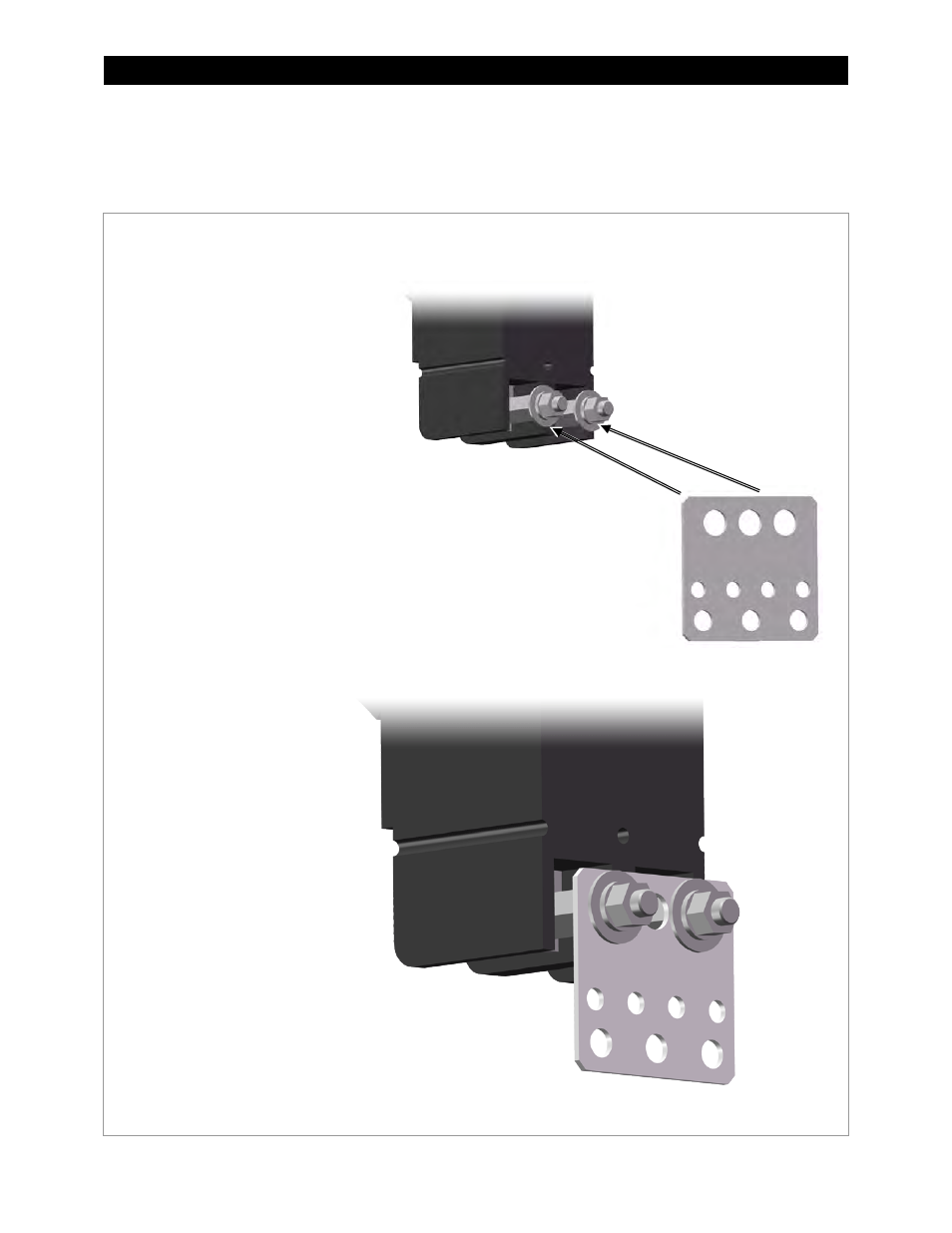
Assembling DC Positive (+) Cable Plate (Bus Bar)
NOTE: These instructions are not used with model GSLCPV1-120/240 and models GSLC175PV1-230.
If using either of these models, proceed to page 21 or the next appropriate instruction.
Figure
18
Assembling the DC Positive (+) Cable Plate
The bottom of each DC disconnect
(circuit breaker) is bolted to a metal
plate (bus bar) which receives the
inverter’s positive (+) battery cables.
To assemble the DC Positive Plate:
1.
Remove the nuts and other hardware
(washer, lock washer, hex nut) from the
bottom terminal in the back of each DC
disconnect.
2.
Place the two DC disconnects side
by side.
3.
Orient the DC positive plate so that the
three largest holes are at the top. These
holes have a diameter of 0.50" (1.3 cm).
Insert the studs on each disconnect
through the first and third holes.
4.
Replace the disconnect hardware
(washer, lock washer, hex nut). Tighten
the nuts to the values shown in Table 1
on page 19. The plate will hold the two
circuit breakers together as a set.