Connections and layout, Continued – Anthem TLP 1 User Manual
Page 10
4
2.2
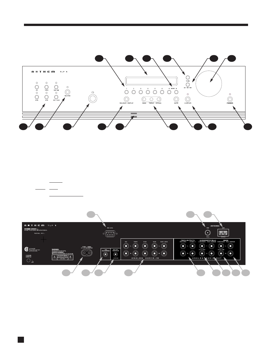
FRONT AND REAR PANEL LAYOUTS
1 – FM•AM Preset selection
2 – Display
3 – FM•AM Seek
4 – FM•AM Tune
5 – FM Stereo / Hi Blend / Mono
6 – Master Control Knob:
• Volume
• Tune for FM•AM
• Setting Adjustment for Bass / Treble / Balance;
Display Brightness; Input Level
7 – Power On / Stand-By
8 – Contour On/Off
9 – Mute
10 – Bass / Treble settings
11 – Front Panel Remote Control IR Sensor
12 – Balance / Display Brightness setting
13 – Headphone Jack
14 – Record Path selection
15 – Source selection
2. CONNECTIONS AND LAYOUT
continued …
13
12
11
15
14
10
9
8
7
6
5
4
2
3
1
1
– RS-232 port (for custom installation)*
2
– FM Antenna Input
3
– AM Antenna Input
4
– Full Range Output (L/R jacks)
5
– High Pass Output (L/R jacks)
6
– 2 Subwoofer Outputs (Full Range)
7
– 2 Subwoofer Outputs (Low Pass)
8
– 2 Line Level Outputs (Record, Zone 2 – L/R jacks)
9
– 5 Inputs (L/R jacks)
10 – Relay Trigger Output (3.5 mm mono jack)
11 – Infra Red Input (3.5 mm mono jack)
12 – Power Cord Connection
3
2
1
12
11
10
9
8
7
6
5
4
*Custom Installers: RS-232 port is on newer production TLP 1s only. Command set is available at www.anthemAV.com.