Sper Scientific 850039 Conductivity TDS Meter - Datalogging User Manual
Page 9
- 9 -
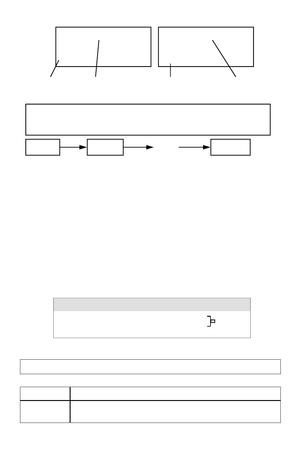
Data 1 Data X+1
Data Z
To Data X To Data Y To Data 16,000
Use the ▲ (5) and ▼ (6) buttons to select the desired memory block num-
ber (1 to 250) and push the SEND (7) button once.
The bottom right of the display shows "Sending Data!".
When the process has finished, "Transmit mode" is displayed.
Push the ESC (3) button to exit this function.
6. RS232 PC SERIAL INTERFACE
The instrument features a 3.5 mm RS232 OUTPUT TERMINAL (15). The
signal output is a 16-digit data stream that can be adapted to user-defined
applications. A RS232 lead with the following connection is required to link
the instrument with the PC serial interface.
Each digit indicates the following status:
D0
End Word = 0D
D1 & D8
Display reading, Dl = LSD, D8 = MSD
(If the display reading is 1234, then D8 to D1 is: 00001234)
Block 1
Block 2
Block 250
………
………
314
uS
xx:xx:xx Transmit Mode
1
uS
1 Transmit Mode
start time the first data memory block start data address
of each block of each block number of each block (1-250)
The 16 digits data stream will be displayed in the following format:
D15 D14 D13 D12 D11 D10 D9 D8 D7 D6 D5 D4 D3 D2 D1 D0
The meter can record up to 16,000 data points, stored in a maximum of
250 memory blocks. All data points saved during one data logging ses-
sion are stored in one memory block.
Meter (3.5 mm jack plug)
PC (9W ‘D” Connector)
Center Pin .................................. Pin 4 Pin 2 2.2 K
Ground/shield ............................ Pin 2 Pin 5 resistor