Idle-eze – Demon Fuel Systems 1563010VE User Manual
Page 10
10
Ensure the engine is at idle and at operating temperature. You may now evaluate the adjustment of
the idle mixture screws. Adjusting the idle mixture usually takes two or more trips around the car.
Turning the screws in, clockwise, reduces the amount of idle fuel and leans the idle mixture. Backing
the screws out increases idle fuel and enriches the idle mixture.
Begin by turning each screw in 1/8 to 1/4 turn at a time. If idle speed decreases, back the screws out
1/8 to 1/4 turn. If idle speed increases, adjust them in again. Adjusting the screws to less than 1 full
turn open can result in an off-idle stumble. However, some engines may respond well and not
stumble with less than one turn.
The goal for best idle quality and throttle response is to have the engine idle with the butterflies
closed, at the correct RPM, with the highest manifold vacuum, and the mixture screws adjusted
between 1 and 2 -1/2 full turns out from fully closed. Again, your particular combination may function
correctly outside of this range.
If you have any further questions concerning the tuning of your carburetor, please contact the tech
staff for more information.
Idle-Eze
The Idle-
Eze™ feature allows you to set your idle speed while maintaining the correct orientation of
the butterflies with the transfer slots. This provides better control of the idle mixture screws, and
results in a cleaner idle, crisper throttle response, and quicker tuning. The Idle-
Eze™ also helps in
overcoming idling difficulties in engines with larger camshafts.
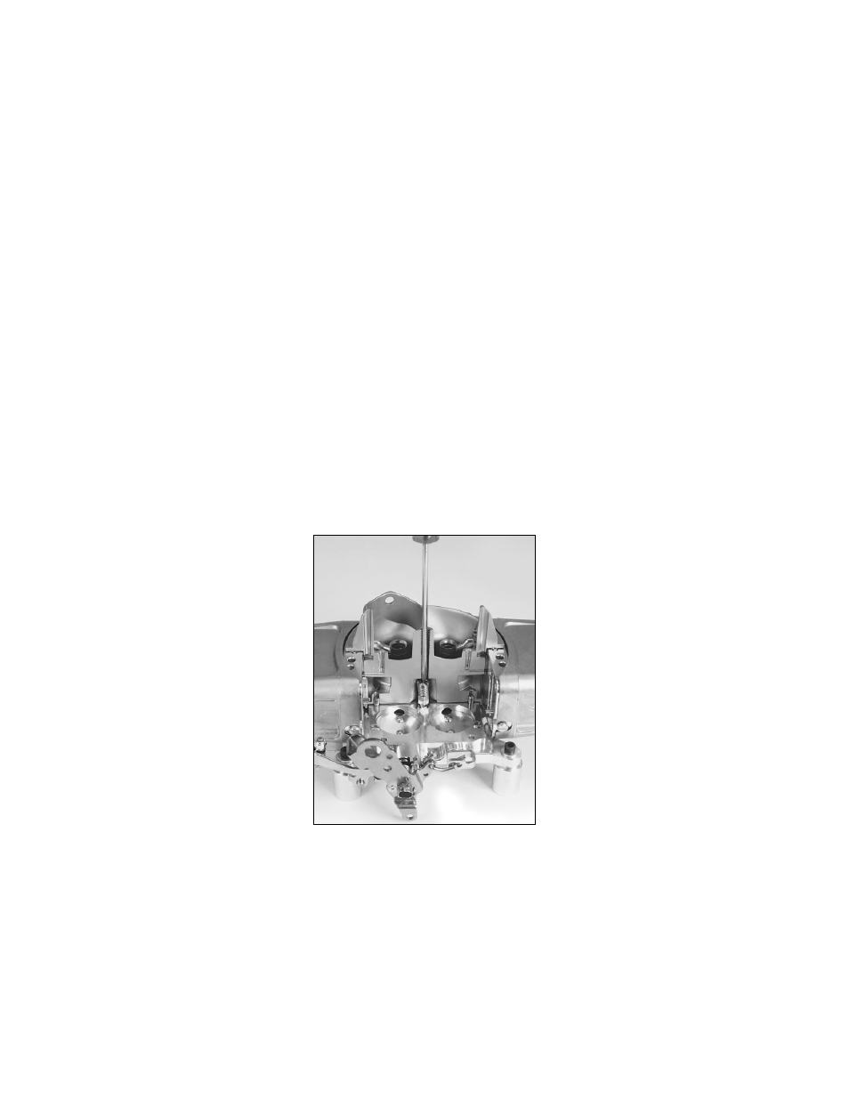
Figure 13
Setup & Tuning instructions:
Adjust the butterflies before installing the carburetor on the engine. On engines that idle at 1000 RPM
or higher, set both the primary and secondary butterflies open by the same amount. As a starting
point (with the carburetor upside down), set the butterflies such that they expose approxi
mately .020”
of the transfer slots. The transfer slots are the thin slots milled in the baseplates and are
approximately 5/16” in length (Fig. 14).