Clinton Electronics CE-CM-LX-17-B User Manual
Page 4
CLINTON Electronics
6701 Clinton Road
Loves Park, IL 61111
1.800.447.3306 Sales
1.800.549.6393 Support
1.800.633.8712 Fax
www.clintonelectronics.com
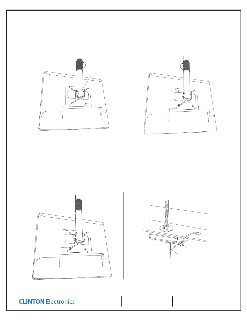
Remove original
M4 x 8mm VESA
screw & replace with
M4 x 10mm screw
U-Bolt Cable Clamp
Cord Management Hole
Hold lower pole section and
turn counter-clockwise to loosen
Prevent display from falling by
holding lower pole section here
Secure assembly by turning collar clockwise:
hand tighten as snug as possible
CAUTION: This stand is intended for use only with the maximum weights indicated.
Use with products heavier than the maximum weights indicated may result in
instability causing possible injury. This product is intended to mount to a steel
support truss, or channel strut.
9/16”
If drilling is nec
essar
y,
U
se 9/16”
metal drill
bit t
o drill thr
ough st
eel
moun
ting sur
fac
e.
Installing the Safety Cable:
1. Run the safety cable into the cable management hole in the top of the pole, and out through the bottom of the pole. The crimped eyelet end
will connect to the LCD.
2. Remove one of the M4 x 8mm VESA mount screws from the LCD-bracket assembly, then connect the crimped eyelet end of the safety cable
to the mount using the supplied M4 x 10mm screw. You can discard the unused M4 x 8mm VESA mount screw that has been removed as it is no
longer needed.
3. Connect the top end of the safety cable by inserting it through a hole in the truss or channel strut, and fasten using the U-Bolt cable clamp. Pull
any remaining slack from the safety cable, and fully tighten the U-Bolt using a 5/16” wrench. Cut or loop any excess cable.
Adjusting Height:
1. Hold the lower pole (where it connects to the LCD) while loosening the center collar by turning it counter-clockwise (see illustration on
left below). Extend the pole by gently lowering it to the desired length.
2. Once the proper length has been maintained, lock the pole in position by rotating the center collar clockwise. The collar should be hand
tightened as snug as possible to prevent the pole from expanding. (see illustration on right below)
Remove original
M4 x 8mm VESA
screw & replace with
M4 x 10mm screw
U-Bolt Cable Clamp
Cord Management Hole
Hold lower pole section and
turn counter-clockwise to loosen
Prevent display from falling by
holding lower pole section here
Secure assembly by turning collar clockwise:
hand tighten as snug as possible
CAUTION: This stand is intended for use only with the maximum weights indicated.
Use with products heavier than the maximum weights indicated may result in
instability causing possible injury. This product is intended to mount to a steel
support truss, or channel strut.
9/16”
If drilling is nec
essar
y,
U
se 9/16”
metal drill
bit t
o drill thr
ough st
eel
moun
ting sur
fac
e.
Loosen
Tighten
v.04.06.11