Assembly instructions, Truss mount or channel strut mount, Max load: 15kgs / 35lbs – Clinton Electronics CE-CM-LX-17-B User Manual
Page 3
Assembly Instructions
Truss mount or channel strut mount
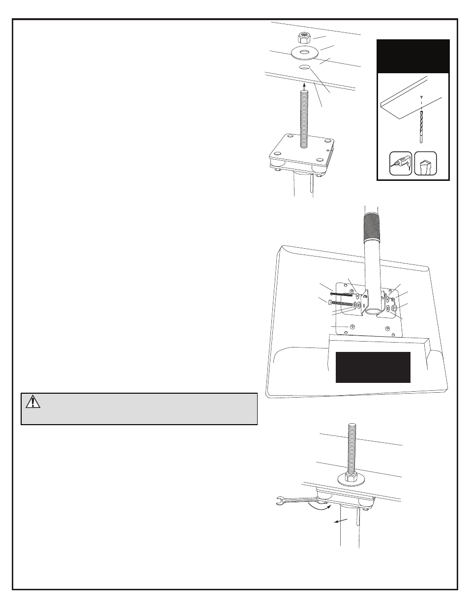
Securing Mount to Building:
1. Insert threaded rod between truss gap or into hole in channel strut.
2. Place 1/2” fender washer over the threaded rod and then 1/2” lock nut.
3. Tighten the 1/2”-13 lock nut using a 3/4” wrench.
7
/
16
10
1/2”-13 Lock Nut
Fender Washer
Truss or Channel Strut
M4 x 8mm
VESA screw
(4 places)
M4 Lock Nut
1/4”-20 Lock Nut
M4 x 45mm
1/4”-20 x 2”
M4 Washer
1/4” Washer
1/4” Washer
M4 Washer
Pole will move in
the direction of the
tightened bolt
1/4” Lock Washer
Min. Hole Size: 1/2”
Max. Hole Size: 5/8”
Min. Steel Thickness: 1/4”
Mounting LCD to Pole:
1. If your LCD is supplied with a VESA plate already mounted on the back, simply
ensure the four M4 screws are in place and tightened. If the mount is not already
attached, connect it using the supplied M4 x 8mm VESA screws (4-places).
*NOTE: Some installations may require running power and video cables
prior to attaching the LCD bracket to the pole. If this is the case, do so
before continuing to step 2.
2. Hold the LCD with attached bracket up to the end of the pole mount, and
line up the wings of the bracket to the holes in the end of the pole. Insert the
1/4”-20 x 2” bolt, lock washer, washers, and lock nut in place according to the
illustration on the right. You will use 7/16” and 10mm wrenches to fully tighten
in step 4.
3. Install the M4 x 45mm screw, washers, and lock nut into the upper slotted hole
according to the illustration on the right. You will use a #2 Phillips screwdriver
and a 7mm wrench to fully tighten in the next step.
4. Tighten the fasteners to secure the monitor at the desired angle.
*NOTE: Avoid overtightening which can cause the pole to indent.
7
/
16
10
1/2”-13 Lock Nut
Fender Washer
Truss or Channel Strut
M4 x 8mm
VESA screw
(4 places)
M4 Lock Nut
1/4”-20 Lock Nut
M4 x 45mm
1/4”-20 x 2”
M4 Washer
1/4” Washer
1/4” Washer
M4 Washer
Pole will move in
the direction of the
tightened bolt
1/4” Lock Washer
Min. Hole Size: 1/2”
Max. Hole Size: 5/8”
Min. Steel Thickness: 1/4”
Leveling the Pole
1. You can ensure the pole is plumb by tightening the 1/4”-20 lock nuts on the top
of the pole where it attaches to the structure using a 7/16” wrench.
2. Place a level on the pole and tighten the nuts that correspond to the direction
that the pole needs to move (see illustration on the right).
3. Check and adjust 2 adjacent sides of the pole until it is plumb in each direction.
7
/
16
10
1/2”-13 Lock Nut
Fender Washer
Truss or Channel Strut
M4 x 8mm
VESA screw
(4 places)
M4 Lock Nut
1/4”-20 Lock Nut
M4 x 45mm
1/4”-20 x 2”
M4 Washer
1/4” Washer
1/4” Washer
M4 Washer
Pole will move in
the direction of the
tightened bolt
1/4” Lock Washer
Min. Hole Size: 1/2”
Max. Hole Size: 5/8”
Min. Steel Thickness: 1/4”
Remove original
M4 x 8mm VESA
screw & replace with
M4 x 10mm screw
U-Bolt Cable Clamp
Cord Management Hole
Hold lower pole section and
turn counter-clockwise to loosen
Prevent display from falling by
holding lower pole section here
Secure assembly by turning collar clockwise:
hand tighten as snug as possible
CAUTION: This stand is intended for use only with the maximum weights indicated.
Use with products heavier than the maximum weights indicated may result in
instability causing possible injury. This product is intended to mount to a steel
support truss, or channel strut.
9/16”
If drilling is nec
essar
y,
U
se 9/16”
metal drill
bit t
o drill thr
ough st
eel
moun
ting sur
fac
e.
Max Load:
15kgs / 35lbs.
Remo
ve or
ig
inal
M4 x 8mm
VESA
scr
ew & r
eplac
e with
M4 x 10mm scr
ew
U-B
olt C
able Clamp
Cor
d M
anagemen
t Hole
Hold lo
w
er pole sec
tion and
tur
n c
oun
ter
-clock
wise t
o loosen
Prev
en
t displa
y fr
om falling b
y
holding lo
w
er pole sec
tion her
e
Secur
e assembly b
y tur
ning c
ollar clock
wise:
hand tigh
ten as snug as possible
CA
UTION
: T
his stand is in
tended f
or use only with the maximum w
eigh
ts indica
ted
.
U
se with pr
oduc
ts hea
vier than the maximum w
eigh
ts indica
ted ma
y r
esult in
instabilit
y causing possible injur
y. T
his pr
oduc
t is in
tended t
o moun
t t
o a st
eel
suppor
t truss
, or channel strut
.
9/16”
If drilling is necessary,
Use 9/16” metal drill
bit to drill through steel
mounting surface.