Boonton PIM 21 User Manual User Manual
Page 10
10 | PIM 21 User’s Manual
Purpose, Function and Features
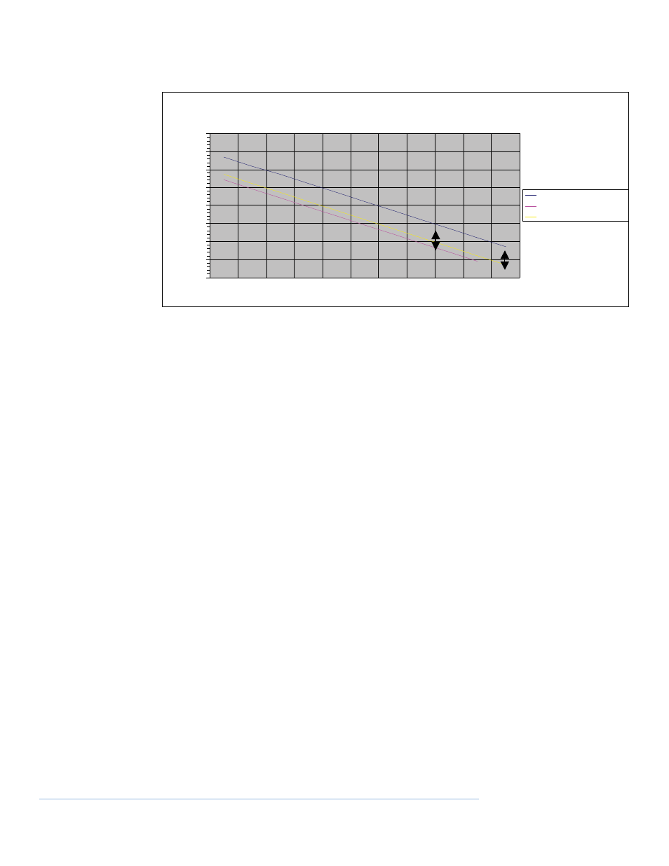
PIM comparison for different carrier powers
Functional Description
The PIM 21 generates two continuous wave carriers at up to 1W / 2W each*. These two carriers
are filtered and combined to a single common test port. The frequencies set in the PIM Test Set
depend on the type and can be customized. For references, please see the table in the adden-
dum.
A receiver is also connected to the common test port via another filter. The receiver is tuned to
the 3rd order Intermodulation product of the two carriers for the measurement of PIM.
Receiver sensitivity is better than -123 dBm, typically -126 dBm.
Functional Block diagram
A microprocessor is used to monitor and control all active modules within the tester. Calibra-
tion tables are stored in non-volatile memory for all critical RF functions i.e. Rx calibration
parameters and excitation carrier power.
* Model Dependent
PIM adjustment chart 1W & 2W vs 20W
-160.00
-150.00
-140.00
-130.00
-120.00
-110.00
-100.00
-90.00
-80.00
PIM Measurement
20 Watt Ref PIM -dBc
1 Watt equivalent PIM -dBc
2Watt equivalent PIM -dBc