Ashland I-110TS User Manual
Page 12
1
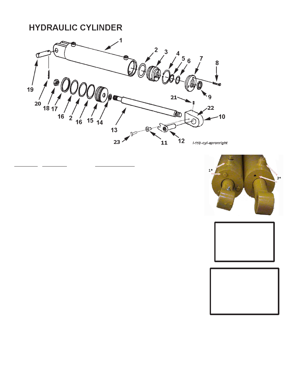
LEFT & RIGHT
APRON CYLINDER
A123319
KEY NO. PART NO.
DESCRIPTION
1
A1H01
Barrel Assembly
A00H0
O-ring seal, ” OD x /1”
A00H11
Head gland
A00H1
Retainer ring
AH1
O-ring, 1-1/” x 1/”
AH1A
Backup washer
A00H1
Head cap
AH1
Capscrew, 1/ NC x 1”
AH1
Wiper seal, 1-1/” ID
10
A1
Block type Apron Cyl. Rod end cyl. 1”
11
A11
Pin keeper bushing
1
A1
Pin: Tab Head
1
A1H0
Shaft, 1-1/” diameter
1
AH0
Piston gasket, 1”
1
A00H0
Piston, ” dia.
1
A00H0
Back up washer, ” OD
1
A00H0
Cast iron ring, ” OD
1
A00H0
Piston nut, 1” NF
1
A11E
Pin, 1” x -1/” w/tab head
0
0
Cotter Pin
1
AFB-000
Allen set screws
22
14505
Grease fitting
AFB-0001
Bolt, 1/” x 1-1/” NC
A00H1B
Packing kit containing:
1 - A00H0 - AH1 - A00H0
1 - AH1A - AH0 1 - AH1
1 - AH0
1* OLD STYLE
The older apron cylinder
can be identified by 3/8”
NPT ports & 3 bolts on the
headcap of the gland.
2* NEW STYLE
The new style, effective
6/25/03, has 7/8” o-ring base
ports & the gland is threaded
into I.D. of the barrel. Identi-
fied by the 2 holes on the end
of the cylinder.