Ashland I-180TS2 User Manual
Page 24
IMPORTANT: This Hyd. Manifold was intergrated into production April, 2006
It replaces A125070 valve.
For older machines see master parts book on Ashlandind.com.
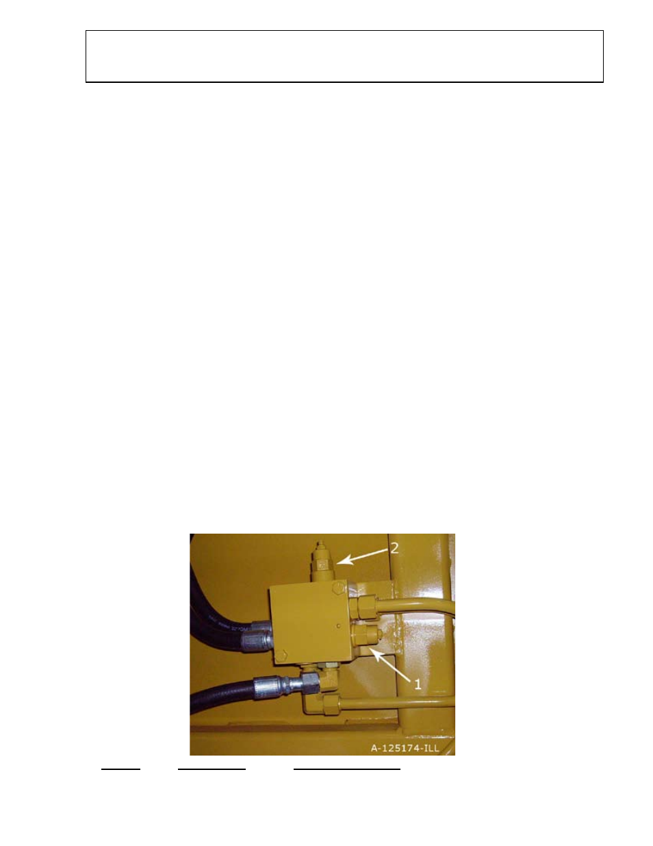
HYDRAULIC MANIFOLD ASSEMBLY
A125174
S.N. 21403 & above
ITEM # PART NO.
DESCRIPTION
1
A125162-01
CENTER BALANCE CARTRIDGE
2
A125162-02 SEQUENCE CARTRIDGE
SETTING THE APRON AND PUSHOFF VALVE
The manifold block containing the pushoff sequence valve cartridge and apron se-
quence valve cartridge is used to control two hydraulic circuits with one hydraulic remote.
when the tractor hydraulic remote is activated, oil flows first to the apron cylinders until
they are fully extended. Once the cylinders are fully extended, the apron circuits’ hydraulic
pressure begins to increase. Once the pressure threshold is surpassed (which is adjust-
able. See adjustment section), the sequence valve diverts the oil flow to the pushoff’s
hydraulic circuit. Once the push off is completely extended the operator then reverses the
tractors hydraulic remote. The counterbalance valve will hold the apron open until the
push off is fully retracted. The Apron sequence valve then opens and allows the apron to
close.
Setting the valves:
STEP 1 PUSHOFF SEQUENCE VALVE
Loosen the lock nut (9/16”) on the sequence valve cartridge. Turn the setscrew
(4mm) clockwise until the front apron rises before the push-off begins to advance. (Earth-
mover should be empty) Turn the adjustment screw an additional 1/4 turn clockwise and
tighten jam nut.
STEP 2 Counter Balance VALVE
Loosen the lock nut (9/16”) on the counterbalance valve cartridge. Turn the set-
screw (4mm) counter-clockwise until the apron holds in a raised position while rear gate is
being retracted. Turn adjustment screw an additional 1/4 turn, tighten jam nut. DO NOT
tighten adjusting screw more than necessary.