10 9b, 13 13a, Warning – American Standard Champion 4 2443 User Manual
Page 4: Care and cleaning
7 3 0 5 2 9 - 10 0 Rev. U
- 4 -
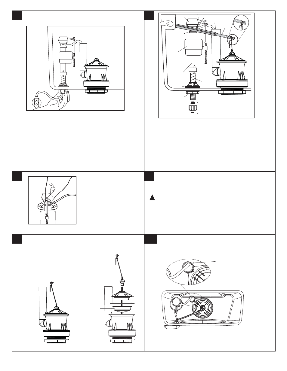
10
9b
ADJUSTMENTS
a. Adjust water level. Water level should be adjusted to level indicated in
tank by adjusting float cup. See Step 11 for water level adjustment method.
IMPORTANT:
b. If bowl fails to siphon, an adjustment may be required with the lift chain.
Simply remove the bead chain from the retainment clip (see Fig. 10A)
and take up slack on the chain, and reinsert on lift rod. Make sure the chain
is not too taught.
With correct washers in
place (see Step 9a),
tighten COUPLING NUT
1/4 turn beyond hand tight.
DO NOT OVERTIGHTEN.
11
1. Turn off water supply and flush toilet to empty tank.
2. Disconnect chain from trip lever by removing hair pin cotter
and clevis pin.
3. Parially lift and support piston bottom with one hand.
4. Remove thumbscrew by turning counter-clockwise.
5. Remove piston top and gasket.
6. Replace gasket with new gasket.
7. Reverse procedure, turn thumbscrew until 2 clicks are felt.
TROUBLE SHOOTING FLUSH VALVE
SEAL REPLACEMENT:
NOTE: DO NOT ADD ANY FOREIGN MATERIALS TO THE SEALING SURFACE.
13
13a
REFILL TUBE REPLACEMENT :
12
When cleaning your toilet, wash it with mild, soapy water, rinse
thoroughly with clear water and dry with a soft cloth.
WARNING:
Do not use in-tank cleaners. These products
can seriously damage fittings in the tank. This damage can
cause leakage and property damage.
American Standard shall not be responsible or liable for
any damage caused by the use of in-tank cleaners.
CARE AND CLEANING
!
Turn on water supply.
Submerge the FLOAT
CUP under the water for
30 seconds. Adjust the
water to desired level by
turning WATER LEVEL
ADJUSTMENT ROD
and moving FLOAT
CUP up or down.
Diagram 1
TANK
LEVER
REFILL
TUBE
TOP
ARM
NIPPLE
PARTS FOR WATER
CONNECTION
(SEE STEP 9)
CONE WASHER
VALVE
BODY
THREADED
SHANK
SHANK
WASHER
COUPLING NUT
(HAND TIGHT ONLY)
FILL
VALVE
FLOAT
CUP
CRITICAL LEVEL
MARK ("C.L.")
MUST BE
1" ABOVE
OVERFLOW PIPE
ADJUSTABLE
HEIGHT
LOCK NUT
Fig. 10A
WATER LEVEL
ADJUSTMENT
ROD
Locate bottom portion of
hose clip to vent tube at
location as shown.
THUMBSCREW
PISTON TOP
PISTON BOTTOM
GASKET
HAIR PIN
COTTER
- Champion 4 2074 CHAMPION 2023 Champion 4 2368 Champion 4 2586 Champion 4 2367 Champion 4 2369 Champion 4 2627 Champion 4 2076 Champion 4 2473 CHAMPION 2002 CHAMPION 2586 CHAMPION 2414 CHAMPION 2586.000ST Champion 4 2792 Champion 4 2058 Champion 4 2793 CHAMPION 3186 CHAMPION 2018 Champion 4 2738 Champion 4 2625 Champion 4 2414 Champion 4 2023 Champion 4 2018 CHAMPION 2585.000ST CHAMPION 2585 Champion 4 2585 CHAMPION 2792 Champion 4 3186