Installation instructions, Warning, Connecting dryer using 3-wire connection – GE GTDL210EDWW User Manual
Page 3: Exhaust information, Exhaust system check list, Never leave the cover off of the terminal block. 3
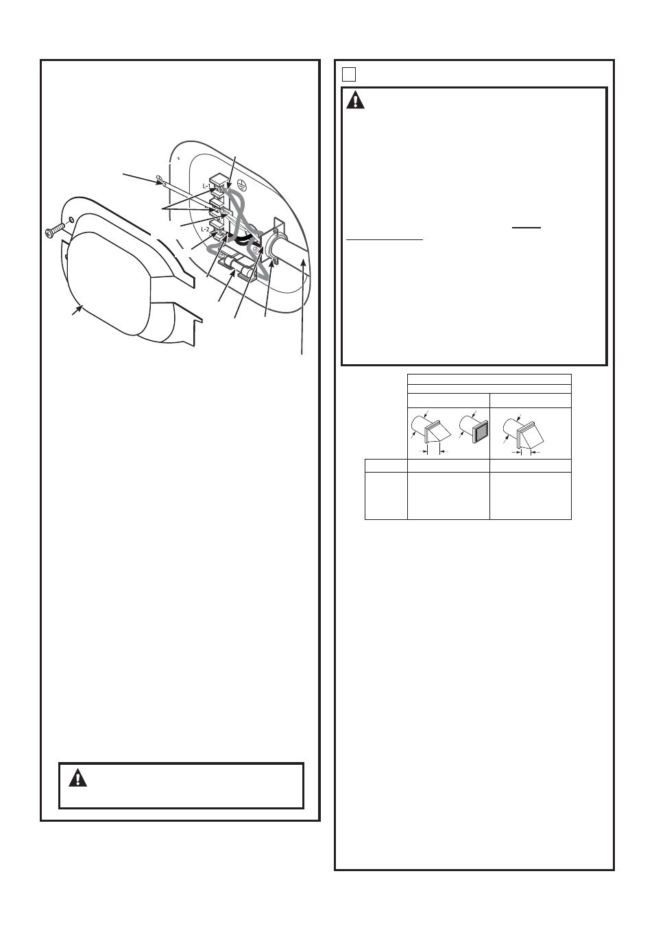
CONNECTING DRYER USING 3-WIRE
CONNECTION
3-wire Connection
Not for use in Canada.
DO NOT use for Mobile Home Installations.
NOT for use on new construction.
NOT for use on recreational vehicles.
NOT for use in areas where local codes prohibit
grounding through the neutral conduction.
7XUQRȺWKHFLUFXLWEUHDNHUVDPSRUUHPRYHWKH
dryer’s circuit fuse at the electrical box.
%HVXUHWKHGU\HUFRUGLVXQSOXJJHGIURPWKHZDOO
5HPRYH WKH SRZHU FRUG FRYHU ORFDWHG DW WKH ORZHU
back.
,QVWDOOLQ8/UHFRJQL]HGVWUDLQUHOLHIWRSRZHUFRUG
HQWU\KROH%ULQJSRZHUFRUGWKURXJKVWUDLQUHOLHI
&RQQHFWSRZHUFRUGDVIROORZV
A. Connect the 2 hot lines to the outer screws of the
WHUPLQDOEORFNPDUNHG/DQG/
%&RQQHFWWKHQHXWUDOZKLWHOLQHWRWKHFHQWHURIWKH
WHUPLQDOEORFNPDUNHG1
%HVXUHJURXQGVWUDSLVFRQQHFWHGWRQHXWUDOFHQWHU
terminal of block and to green ground screw on
FDELQHW UHDU 7LJKWHQ DOO WHUPLQDO EORFN VFUHZV
securely.
7. Properly secure power cord to strain relief.
5HLQVWDOOWKHFRYHU
WARNING:
NEVER LEAVE THE
COVER OFF OF THE TERMINAL BLOCK.
3
EXHAUST INFORMATION
WARNING -
IN CANADA AND IN THE
UNITED STATES, THE REQUIRED EXHAUST
DUCT DIAMETER IS 4 in (102mm). DO NOT
USE DUCT LONGER THAN SPECIFIED IN THE
EXHAUST LENGTH TABLE.
8VLQJH[KDXVWORQJHUWKDQVSHFL¿HGOHQJWKZLOO
• Increase the drying times and the energy cost.
5HGXFHWKHGU\HUOLIH
$FFXPXODWHOLQWFUHDWLQJDSRWHQWLDO¿UHKD]DUG
The correct exhaust installation is YOUR
RESPONSIBILITY. Problems due to incorrect
installation are not covered by the warranty.
5HPRYHDQGGLVFDUGH[LVWLQJSODVWLFRUPHWDOIRLO
transition duct and replace with UL listed transition
duct.
The MAXIMUM ALLOWABLE duct length and number of
bends of the exhaust system depends upon the type of
GXFWQXPEHURIWXUQVWKHW\SHRIH[KDXVWKRRGZDOO
FDSDQGDOOFRQGLWLRQVQRWHGEHORZ7KHPD[LPXP
duct length for rigid metal duct is shown in the table
below.
4" DIA.
4"
4" DIA.
4" DIA.
2-1/2"
RECOMMENDED MAXIMUM LENGTH
Exhaust Hood Types
Recommended
No. of 90°
Elbows
Rigid
Metal
Rigid
Metal
150 Feet
135 Feet
125 Feet
115 Feet
105 Feet
125 Feet
115 Feet
105 Feet
95 Feet
85 Feet
0
1
2
3
4
Use only for short
run installations
5
95 Feet
75 Feet
• )RUHYHU\H[WUDHOERZUHGXFHWKHDOORZDEOHYHQWV\VWHP
OHQJWKE\IW
• 7ZRHOERZVZLOOEHWUHDWHGOLNHRQHHOERZ
• )RUWKHVLGHH[KDXVWLQVWDOODWLRQVDGGRQHHOERZWRWKH
chart.
• The total vent system length includes all the straight portions
DQGHOERZVRIWKHV\VWHPWUDQVLWLRQGXFWLQFOXGHG
EXHAUST SYSTEM CHECK LIST
HOOD OR WALL CAP
• Terminate in a manner to prevent back drafts or entry of
birds or other wildlife.
• Termination should present minimal resistance to the
H[KDXVWDLUÀRZDQGVKRXOGUHTXLUHOLWWOHRUQRPDLQWHQDQFH
to prevent clogging.
• Never install a screen in or over the exhaust duct. This
could cause lint build up.
:DOOFDSVPXVWEHLQVWDOOHGDWOHDVWLQDERYHJURXQG
level or any other obstruction with the opening pointed
down.
SEPARATION OF TURNS
For best performance, separate all turns by at least 4 ft.
of straight duct, including distance between last turn and
exhaust hood.
TURNS OTHER THAN 90º
2QHWXUQRIRUOHVVPD\EHLJQRUHG
7ZRWXUQVVKRXOGEHWUHDWHGDVRQHWXUQ
(DFKWXUQRYHUVKRXOGEHWUHDWHGDVRQHWXUQ
Installation Instructions
Screws
Hot
Wire
µ8/
5HFRJQL]HG
6WUDLQ5HOLHI
$:*PLQLPXPFRSSHUFRQGXFWRUVRU9$SRZHUVXSSO\
cord kit marked for use with dryers and provided with closed loop or
VSDGHWHUPLQDOVZLWKXSWXUQHGHQGVQRWVXSSOLHG
Fuse
Hot
Wire
Neutral
ZKLWH
Strain
5HOLHI
%UDFNHW
Cover
Screw
,IUHTXLUHGE\ORFDOFRGHLQVWDOOH[WHUQDOJURXQGQRWSURYLGHG
to grounded metal, cold water pipe, or other established ground
determined by a qualified electrician.
Green Ground Screw
& Ground Strap