Installation instructions, Warning, Preparing for installation of new dryer – GE GTDL210EDWW User Manual
Page 2: Removing lint from wall exhaust opening, Electrical connection information, Electrical requirements, Grounding instructions
Minimum Clearance Other Than Alcove or Closet Installation
0LQLPXPFOHDUDQFHWRFRPEXVWLEOHVXUIDFHVDQGIRUDLURSHQLQJDUHLQFOHDUDQFHERWKVLGHVDQGLQUHDU
Consideration must be given to provide adequate clearance for installation and service.
1
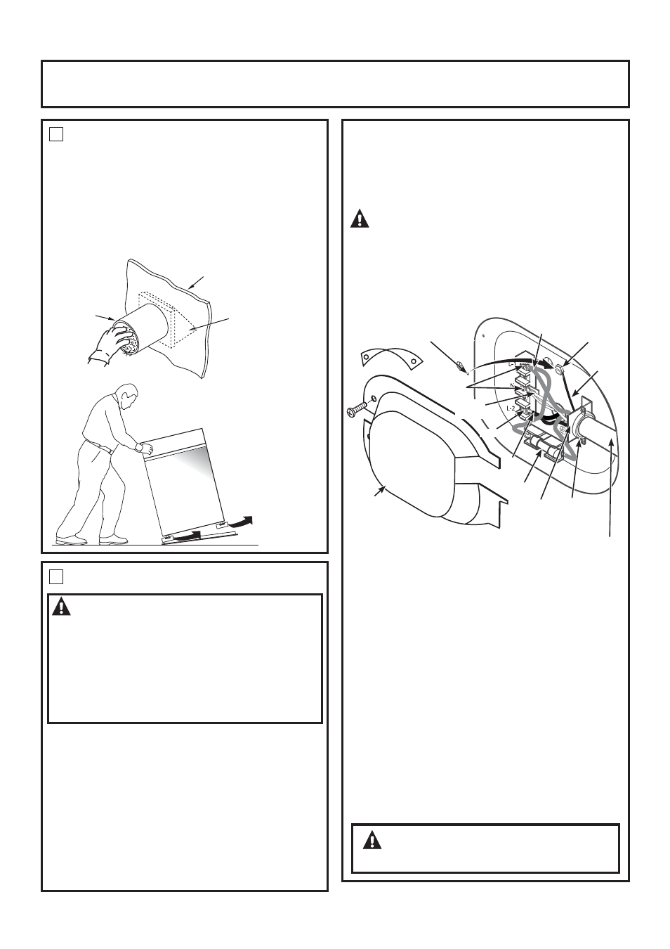
PREPARING FOR INSTALLATION OF
NEW DRYER
TIP: Install your dryer before installing your washer. This
will allow better access when installing dryer exhaust.
REMOVING LINT FROM WALL EXHAUST
OPENING
• Remove and discard existing plastic or metal foil
transition duct and replace with UL listed transition
duct.
2
ELECTRICAL CONNECTION INFORMATION
WARNING-
TO REDUCE THE RISK OF
FIRE, ELECTRICAL SHOCK AND PERSONAL INJURY:
• DO NOT USE AN EXTENSION CORD OR AN
ADAPTER PLUG WITH THIS APPLIANCE.
Dryer must be electrically grounded in accordance with
local codes and ordinances, or in the absence of local
codes, in accordance with the NATIONAL ELECTRICAL
CODE, ANSI/NFPA NO. 70.
CONNECTING DRYER USING 4-WIRE
CONNECTION (MUST BE USED FOR
MOBILE HOME INSTALLATION)
NOTE: Since January 1,1996, the National Electric code
requires that the new constructions utilize a 4-wire
connection to an electric dryer.
WARNING:
Only a 4-conductor cord shall be used when the
appliance is installed in a location where grounding
through the neutral conductor is prohibited. Grounding
through the neutral is prohibited for the new branch-
circuit installations, mobile homes, recreational
vehicles, and areas where local codes prohibit
grounding through the neutral conduction.
7XUQRȺWKHFLUFXLWEUHDNHUVDPSRUUHPRYHWKH
dryer’s circuit fuse at the electrical box.
%H VXUH WKH GU\HU FRUG LV XQSOXJJHG IURP WKH ZDOO
receptacle.
5HPRYHWKHSRZHUFRUGFRYHUORFDWHGDWWKHORZHU
back.
5HPRYH DQG GLVFDUG JURXQG VWUDS .HHS WKH JUHHQ
ground screw for step 7.
,QVWDOOLQ8/UHFRJQL]HGVWUDLQUHOLHIWRSRZHUFRUG
HQWU\KROH%ULQJSRZHUFRUGWKURXJKVWUDLQUHOLHI
&RQQHFWSRZHUFRUGDVIROORZV
A. Connect the 2 hot lines to the outer screws of
WKHWHUPLQDOEORFNPDUNHG/DQG/
%&RQQHFWWKHQHXWUDOZKLWHOLQHWRWKHFHQWHURI
WKHWHUPLQDOEORFNPDUNHG1
7. Attach ground wire of power cord with the green
JURXQG VFUHZ KROH DERYH VWUDLQ UHOLHI EUDFNHW
7LJKWHQDOOWHUPLQDOEORFNVFUHZVVHFXUHO\
8. Properly secure power cord to strain relief.
5HLQVWDOOWKHFRYHU
INTERNAL DUCT
OPENING
CHECK THAT EXHAUST
HOOD DAMPER OPENS
AND CLOSES FREELY.
WALL
TILT THE DRYER SIDEWAYS
AND REMOVE THE FOAM
SHIPPING PADS BY
PULLING AT THE SIDES
AND BREAKING THEM
AWAY FROM THE DRYER
LEGS. BE SURE TO
REMOVE ALL OF THE
FOAM PIECES AROUND
THE LEGS.
ELECTRICAL REQUIREMENTS
This dryer must be connected to an individual branch
FLUFXLW SURWHFWHG E\ WKH UHTXLUHG WLPHGHOD\ IXVHV RU
FLUFXLW EUHDNHUV $ IRXU RU WKUHHZLUH VLQJOH SKDVH
9RU9+]DPSFLUFXLWLVUHTXLUHG
GROUNDING INSTRUCTIONS
This dryer must be connected to a grounded metal,
SHUPDQHQW ZLULQJ V\VWHP RU DQ HTXLSPHQWJURXQGLQJ
conductor must be run with the circuit conductors and
connected to the equipment grounding terminal on the
appliance.
WARNING:
NEVER LEAVE THE
COVER OFF OF THE TERMINAL BLOCK.
Installation Instructions
2
Screws
5HPRYHJURXQGVWUDS
and discard. Keep
green ground screw
Hot
Wire
5HORFDWH
green
ground
screw
here
Green
Wire
µ8/
5HFRJQL]HG
6WUDLQ5HOLHI
$:*PLQLPXPFRSSHUFRQGXFWRUVRU9$SRZHUVXSSO\
cord kit marked for use with dryers and provided with closed loop or
VSDGHWHUPLQDOVZLWKXSWXUQHGHQGVQRWVXSSOLHG
Fuse
Hot
Wire
Neutral
ZKLWH
Strain
5HOLHI
%UDFNHW
Cover
Screw