Figure 2-1 – Apple iMac User Manual
Page 22
C H A P T E R 2
Architecture
22
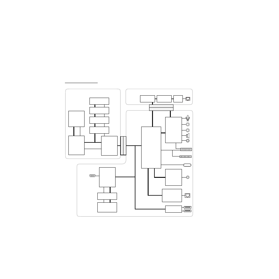
The components at the heart of the iMac computer reside on two printed-circuit
boards: the main logic board and the processor module. The Figure 2-1 is a
block diagram showing the major components on those boards. The
components shown are described in the sections that follow.
Figure 2-1
Block diagram
Power switch
and LED
Sound in
Sound out
IrDA board
Rage IIc
video
DAC
Internal
video
monitor
SGRAM
Cuda
power
manager
IC
Internal IDE
disk drive
PCI bus
Main logic board
SGRAM
SO-DIMM
Processor module
Grackle
memory
controller
and PCI
bus bridge
PowerPC
G3
micro-
processor
512 KB
Backside
L2 cache
Address
Data
ROM
RAM
RAM
SO-DIMM
RAM
SO-DIMM
Modem module
Telephone
connector
Internal
CD-ROM drive
Ethernet
connector
Internal
microphone
Speakers
Headphone
jack board
ST10040
Ethernet IC
Datapump
DAA
Paddington
I/O and
disk
controller
Burgundy
sound I/O
USB port 1
USB port 2
USB IC
Modem
controller
- iMac G5 (2005) (96 pages)
- iMac G5 (96 pages)
- iMac (6 pages)
- Mac Pro Computer (92 pages)
- Mac Pro (88 pages)
- Mac mini (96 pages)
- Mac mini (original) (106 pages)
- eMac (80 pages)
- eMac (10 pages)
- Power Mac G5 (Late 2005) (33 pages)
- Power Mac G5 (Early 2005) (120 pages)
- iMac G3 (38 pages)
- Intel-based iMac (Mid 2007) (76 pages)
- iMac G5 (iSight) (96 pages)
- Mac mini (Early 2006) (96 pages)
- Power Mac G5 (36 pages)
- Power Mac G5 (112 pages)
- Mac mini (Intel-based; Mid 2007) (72 pages)
- PowerPC G5 (15 pages)
- Macintosh Performa 578 (161 pages)
- Xserve G5 (96 pages)
- Xserve G5 (94 pages)
- Xserve (Hard Drive Replacement) (3 pages)
- Workgroup Server 8550 (121 pages)
- Workgroup Server 8550 (163 pages)
- iMac computer (120 pages)
- LC 560 (2 pages)
- Mac G4 (Video Card Replacement) (6 pages)
- Mac 6500/275 (232 pages)
- Mac Performa 5300 CD series (Tech informatiom) (8 pages)
- Power Macintosh 6500 Series (260 pages)
- eMac (Stand Installation) (13 pages)
- Remote Desktop (116 pages)
- Remote Desktop (203 pages)
- Remote Desktop (16 pages)
- MAC PRO (Hard Drive Replacement) (5 pages)
- iMac G5, 20-inch (314 pages)
- iMac G5, 20-inch (22 pages)
- Power Macintosh 7100/66AV (132 pages)
- Xserve Late 2006/Early 2008 (PCI Expansion Card Replacement) (6 pages)
- Xserve (Blower Replacement) (5 pages)
- Xserve RAID (Locking Switch Replacement) (6 pages)
- Macintosh Performa 640 Series (DOS Compatible) (196 pages)
- Mac 9600 (237 pages)