A.O. Smith TC-099 User Manual
Page 40
AOS WPC - Tech Training
39 of 72
Ashland City, TN © 2007
Servicing should only be performed by a Qualified Service Agent
VF BOILER SERVICE MANUAL
PDB - SECTION D
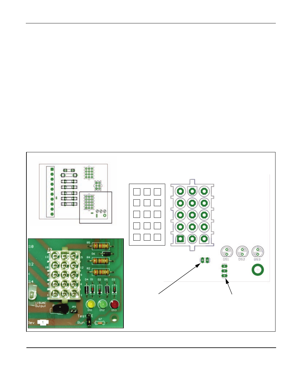
The lower right corner of the PDB contains the J3 Socket and the JP1 jumper. The J3 Socket
is described here the JP1 jumper is described on page 40.
J3 Socket (120 VAC Outputs)
• Pin 1 - 120 VAC Hot to MCB J1 Socket
• Pin 2 - 120 VAC Neutral to MCB J1 Socket
• Pin 3 - Earth Ground to MCB J1 Socket
• Pin 4 - 120 VAC Hot to VFD Input Terminals (page 11)
• Pin 5 - 120 VAC Neutral to VFD Input Terminals (page 11)
• Pin 6 - Earth Ground to VFD Input Terminals (page 11)
• Pin 7 - Spare 120 VAC Hot
• Pin 8 - Spare 120 VAC Neutral
• Pin 9 - Spare Earth Ground
• Pin 10 - Spare 120 VAC Hot
• Pin 11 - Spare 120 VAC Neutral
• Pin 12 - Spare Earth Ground
• Pin 13 - Spare 120 VAC Hot
• Pin 14 - Spare 120 VAC Neutral
• Pin 15 - Spare Earth Ground
JP1 Jumper
Power Test Jumper
(see page 40)
D
3
2
1
6
5
4
9
8
7
12
11
10
15
14
13
J3 Pin Numbers
J3 Socket
120 VAC Outputs
JP1
JP3 Jumper
Should be on - removed
during manufacturing only
JP3