System board components, System maintenance switch – HP ProLiant DL320 G5 Server User Manual
Page 11
Component identification 11
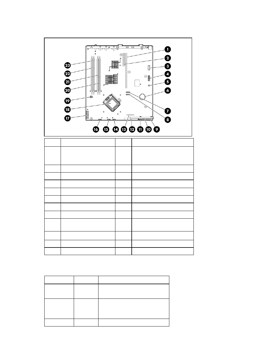
System board components
Item Description
Item Description
1
PCI Express x8 connector
or optional PCI-X 133-MHz
connector
13
Diskette drive connector
2
PCI Express x1 connector
14
Fan 3 and 4 connector
3
Video option connector
15
Fan 5 and 6 connector
4
System maintenance switch 16
Fan 7 and 8 connector
5
NMI switch
17
Main power connector
6 Battery
18 Processor
socket
7
Hard drive connector 1
19
Auxiliary power connector
8
Hard drive connector 2
20
DIMM slot 1 (bank A)
9
Front panel LED board
connector
21
DIMM slot 2 (bank B)
10
Front USB connector
22
DIMM slot 3 (bank A)
11
Fan 1 and 2 connector
23
DIMM slot 4 (bank B)
12
Optical drive connector
—
—
System maintenance switch
Position Default
Function
S1
Off
Off = iLO 2 security is enabled
On = iLO 2 security is disabled
S2
Off
Off = Normal operation
On = RBSU will not commit any
configuration changes *
S3 Off
Reserved
- xt1500 (58 pages)
- LaserJet 4700 (68 pages)
- ProLiant BL460c Gen8 Server Blade (67 pages)
- ProLiant DL360 Server (16 pages)
- ProLiant BL460c Gen8 Server Blade (65 pages)
- ProLiant DL388p Gen8 Server (128 pages)
- ProLiant DL388p Gen8 Server (47 pages)
- ProLiant BL40p Server series (73 pages)
- ProLiant BL465c Server Blade (87 pages)
- ProLiant ML115 Server (63 pages)
- ProLiant DL140 G2 Server (81 pages)
- Servidor HP ProLiant ML370 G4 (20 pages)
- Servidor HP ProLiant ML370 G4 (30 pages)
- Servidor HP ProLiant DL160 G5p (84 pages)
- Servidor HP ProLiant DL980 G7 (143 pages)
- Servidor HP ProLiant DL380 G5 (137 pages)
- Integrity rx2620 Servers (37 pages)
- Integrity Superdome sx1000 Server (53 pages)
- Integrity rx2620 Servers (37 pages)
- Integrity rx2620 Servers (58 pages)
- Integrity rx2620 Servers (77 pages)
- Integrity rx2620 Servers (107 pages)
- Integrity rx2620 Servers (55 pages)
- 9000 rp3440 Servers (36 pages)
- Integrity rx2620 Servers (42 pages)
- Integrity rx2620 Servers (48 pages)
- Integrity rx2620 Servers (53 pages)
- Integrity rx2620 Servers (24 pages)
- Integrity rx2620 Servers (33 pages)
- Integrity rx2620 Servers (100 pages)
- Servidor HP ProLiant DL360p Gen8 (129 pages)
- Servidor HP ProLiant DL120 G6 (133 pages)
- ProLiant DL580 Gen8 Server (91 pages)
- ProLiant MicroServer Gen8 (95 pages)
- ProLiant MicroServer (94 pages)
- ProLiant BL685c G5 Server Blade (99 pages)
- ProLiant Firmware Maintenance CD (87 pages)
- ProLiant BL10e Server Blade (232 pages)
- ProLiant BL40p Server series (30 pages)
- Serveur lame HP ProLiant BL680c G5 (90 pages)
- Serveur lame HP ProLiant BL465c Gen8 (578 pages)
- ProLiant DL320e Gen8 Server (96 pages)
- ProLiant ML110 G7 Server (113 pages)
- 9000 rp8420 Servers (38 pages)
- Integrity Superdome sx1000 Server (19 pages)