Installation, Figure 25 – Alliance Laundry Systems BF50PV User Manual
Page 41
39
Installation
F232058
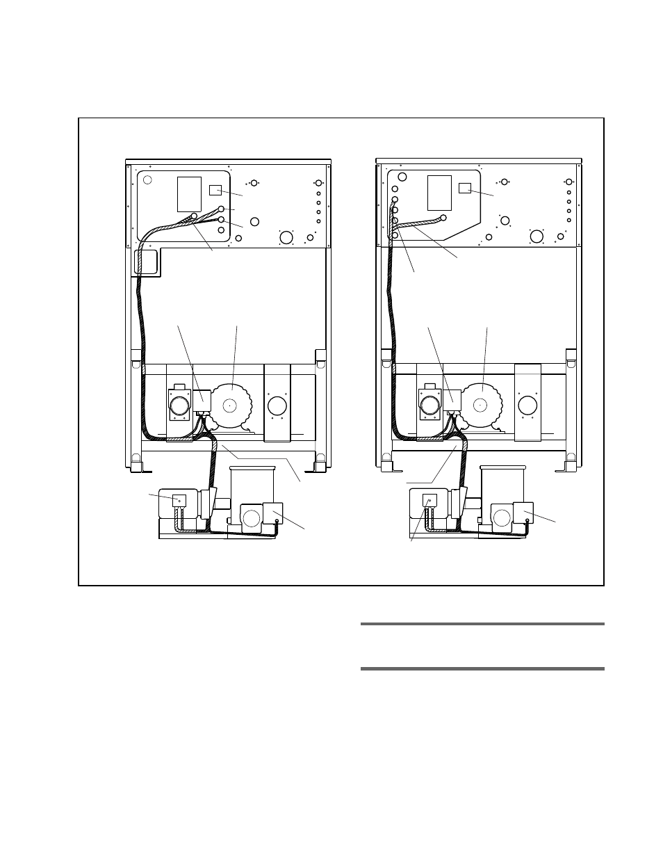
Figure 25
35 – 50 LB Models
85 LB Models
AC
Drive
XFMR
4-Conductor Cable
Main Drive Motor Cable
(Factory Installed)
Filter
Tank
Pump Motor
Junction Box
Tank
Drain Valve
AC
Drive
XFMR
Main Drive Motor Cable
(Factory Installed)
Filter
Tank
Pump Motor
Junction Box
Tank
Drain Valve
Route Cable Under Frame Then
Around To Top Of Frame.
Follow Main Drive Motor Cable
Route to AC Drive Module
Main
Drive Motor
Sewer
Drain Valve
Main
Drive Motor
Sewer
Drain Valve
2-Conductor Cable
And 4-Conductor Cable
Wet Clean Module Cable Routing
2-Conductor
Cable
R009I
c. Route 4-conductor and 2-conductor
cables along the frame of the washer-
extractor, following the same routing as
the main drive motor cable. Allow
sufficient clearance between the cables
and any moving parts of the washer-
extractor. See Figure 25.
Note:
Route cables underneath the frame as
shown in Figure 25.