2 relay interface, 13 voltage measurement interface, 1 gpio – Atmel AVR2016 User Manual
Page 9: Relay interface, Voltage measurement interface, Gpio
Atmel AVR2016: RZRAVEN Hardware User’s Guide [APPLICATION NOTE]
8117E
−AVR−07/12
9
ISP programming can be performed by connecting an ISP enabled Atmel AVR programming tool to the pin header J302
(ATmega3290P) and J205 (ATmega1284P). AVR tools like Atmel STK
®
500, AVRISP mkII and JTAGICE mkII can be
used for this.
The AVRRAVEN does not come with these headers mounted. So it is up to the user populating these. Wires could also
be soldered in instead of the dual row headers.
2.12.2 Relay Interface
A relay interface (Relay Positive and Negative) is available through J401. This interface can be used with the
AVRRAVEN running from external power. A switching transistor is connected to PB6 on the ATmega3290P so that
sufficient current can be provided to the relay being driven. An external power source must be used if the relay option is
required. The AVRRAVEN must then be supplied with the rated voltage of the relay.
2.13
Voltage Measurement Interface
Two of the pins in header J401 can be used for external voltage measurements, however only one at the time. The
possible voltage ranges are 0 to VCC or via a voltage divider giving an approximate range of 0 to five times VCC. A
simple voltage divider is implemented to scale the measurement voltage. A diode bridge is also used to prevent reverse
polarity and to protect the ATmega3290P’s ADC channel 3.
2.13.1 GPIO
Both the Atmel ATmega3290P and Atmel ATmega1284P are high pin count devices, and a number of these are not
used. These pins are available through the user I/O headers; J401, J201, J202 and J203. See
for further details.
Be aware that these pins do not have level converters and should thus not be connected directly to an application board
running on a different voltage level than the Atmel AVRRAVEN.
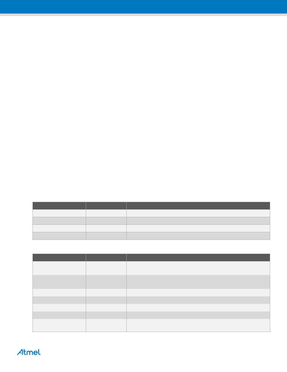
Table 2-2. ATmega3290P User I/O.
ATmega3290P Port Pin
PCB Connection
Comment
PE3
J401-8
Via 470Ω series resistor and10kΩ pull-up
PE4
J401-9
Via 470Ω series resistor and10kΩ pull-up
PE5
J401-10
Via 470Ω series resistor and10kΩ pull-up
PE6
J401-11
Via 470Ω series resistor and10kΩ pull-up
Table 2-3. ATmega1284P User I/O.
ATmega1284P User I/O
PCB Connection
Comment
PC0
J201-1
TWI SCL.
Connected to serial EEPROM
PC1
J201-2
TWI SDA.
Connected to serial EEPROM
PC2
J201-3
JTAG TCK.
PC3
J201-4
JTAG TMS.
PC4
J201-5
JTAG TDO.
PC5
J201-6
JTAG TDI.
N.C.
J201-7
Populate R204 to connect to PC6. RTC Xtal XC202 must then be
removed.