Alloy Computer Products POE120 Series User Manual
Page 8
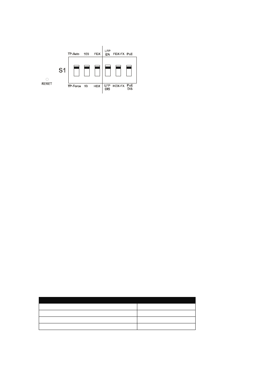
9. DIP Switch Configuration
Fig. 11 Reset button and S1 – Bit 1, 2, 3, 4, 5, 6, Configuration and Settings
Reset
: If S1-1, S1-2, S1-3, S1-4 or S1- status is
changed, please press this button for your
settings to take effect.
S1-1 TP Port Mode
: AUTO(Default) or FORCE
S1-2 TP Port Speed
: 100 or 10 when TP at Force
S1-3 TP Port Duplex
: FDX or HDX when TP at Force
S1-4 LFP
: LFP Enabled (Default) or Disabled
S1-5 Fibre Port Duplex
: 100FDX (Default) or 100HDX
S1-6 POE ON/OFF
: Enabled (Default) or Disabled
Note:
1. S1-2 and S1-3 will take effect only when S1-1 is set to TP-Force
2. S1-5 must be set to 100FDX for Single Fibre Model
3. S1-6 must be set to POE when you need to supply power to a PD.
Warning:
- When a Copper port set to AUTO and is connected to a device that is
Forced to 100Mbps FDX , instead of a device running NWAY, it may
result in the devices connecting in HDX mode, this may cause packet
collisions on your network.
- Please ensure that all network nodes that this device connects to are
set to the same mode at each end of the link.
e.g., Both ends are set to Auto-Negotiation mode (AUTO)
10. Cable Distances and Limitations
- TP Cable Limitations: Cat 5 up to 100m
- Fibre Cable Limitations:
SC/ST Converter Models
Multi Mode Half Duplex
412m
Multi Mode Full Duplex
2Km
Single Mode Half Duplex
412m
Single Mode Half Duplex 5/20/40/60/80/100Km