Correct incorrect, Installation instructions, Using push-in fittings – Water Inc BG 1000 User Manual
Page 4
For Use With Cold Water Only.
NOTE: Remove items from under the sink. Place catch basin there to collect small amounts of water that may run out
when disconnecting water supply lines.
1. Turn off cold water supply valve.
Install (2) quick connect fittings into head assembly using PTFE thread tape only.
2. Remove cold side riser tubing connection at angle stop. Install Quick Connect
riser adapter to angle stop and reconnect riser tube to the quick connect riser
adapter.
3. Select and mark a location under the sink that allows access for filter change.
Measure dimensions of location for filter to allow for the following min/max
space: 6” W X 5 ½” D X 19” H (note: if the cartridge is too tall for the base of
the cabinet, a hole can be cut to allow for the filter to be changed).
4. Using filter head/bracket as a guide, mark hole locations so that there is 1 1/2”
between the screws (see Figure 1), from center of each screw.
Install screws and washers, but only halfway, so you can
easily slip the bracket to wall before firmly setting screws.
When installed, the bottom of the filter should have a
minimum clearance of 2 1/2” from sink cabinet floor to
facilitate cartridge change.
Fasten Filter Head Assembly to wall with Phillips head mounting
screws supplied.
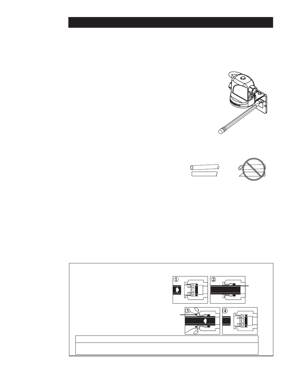
5. Cut tubing straight with a razor knife or tube cutter.
(See Figure 2).
Determine length of tubing required from filter head/bracket to faucet and from water supply line to filter
head/bracket by holding tubing in place ensuring it is of appropriate length. Do not kink tubing as this will impede
water flow. If necessary, loop tubing around to avoid it being kinked.
Connect 1/4” tubing from riser adapter to inlet side of filter head. (See “Using Push-In Fittings.)
Install optional ball valve in line from water supply to filter head bracket.
BG-12000 Only: Install and mount PID (required) per
instructions in section “Operation Instructions For The Digiflow 8800T Performance Indicator Device (PID).
Correct
Incorrect
Figure 2
Collet
Backstop
“Using Push-In Fittings”
To Attach Tubing
(1) Push tubing in as far as it will go.
(2) Tubing must be inserted past o-ring and hit backstop.
Pull tube to ensure it is secured.
To Release Tubing
(3) Push in collet to release tubing.
(4) With collet held, pull tubing straight out.
INSTALLATION INSTRUCTIONS
Figure 1
CAUTION
To reduce the risk associated with property damage due to water leakage:
• Ensure all tubing and fittings are secure and free of leaks.
— 4 —