Anaheim CLCI2000 User Manual
Page 11
8
DIRECTION SIGNALS
This output is TTL/CMOS compatible. The source current rating (Voh = 2.7 V) is 12mA. The sink current rating (Vol =
0.5 V) is 9mA. The Direction signal is +5VDC for '+' or clockwise motion, and 0VDC for '-' or counterclockwise motion.
SOFT LIMIT
This input will cause the motor to ramp down to the base speed. This input contains a 2.5K pullup resistor to +5VDC.
It should be activated by connecting it to the 0VDC pin, or a logic level that can sink 2.0mA at TTL levels.
HOME LIMIT
This is similar to the Hard Limit. It will cause the motor to stop without ramping down. This input contains a 2.5K pullup
resistor to +5VDC. It should be activated by connecting it to the 0VDC pin, or a logic level that can sink 2.0mA at TTL
levels. See the Command Dictionary Section for more information.
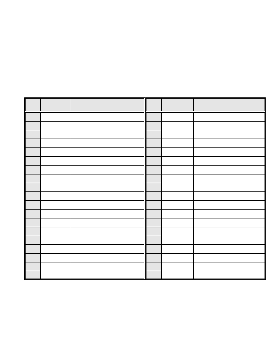
PIN
DESCRIPTION
PIN
FUNCTION
DESCRIPTION
FUNCTION
1
+5VDC
5 VOLT DC OUTPUT
20
C:SOFT-
C: - SOFT LIMIT SWITCH
2
OUT6
OUTPUT 6
21
C:HOME+
C: + HOME LIMIT SWITCH
3
OUT7
OUTPUT 7
22
C:HOME-
C: - HOME LIMIT SWITCH
4
OUT8
OUTPUT 8
23
C:HARD+
C: + HARD LIMIT SWITCH
5
OUT9
OUTPUT 9
24
C:HARD-
C: - HARD LIMIT SWITCH
6
OUT10
OUTPUT 10
25
0 VDC
O VOLT DC REFERENCE
7
0VDC
0 VOLT DC
26
D:CLOCK
D: CLOCK
8
IN6
INPUT 6
27
D:DIR
D: DIRECTION
9
IN7
INPUT 7
28
D:EA
D: ENCODER CHANNEL A
10
IN8
INPUT 8
29
D:EB
D: ENCODER CHANNEL B
11
IN9
INPUT 9
30
D:EZ
D: ENCODER CHANNEL Z
12
IN10
INPUT 10
31
D:SOFT+
D: + SOFT LIMIT SWITCH
13
C:CLOCK
C: CLOCK
32
D:SOFT-
D: - SOFT LIMIT SWITCH
14
C:DIR
C: DIRECTION
33
D:HOME+
D: + HOME LIMIT SWITCH
15
C:EA
C: ENCODER CH. A
34
D:HOME-
D: - HOME LIMIT SWITCH
16
C:EB
C: ENCODER CH. B
35
D:HARD+
D: + HARD LIMIT SWITCH
17
C:EZ
C: ENCODER CH. Z
36
D:HARD-
D: - HARD LIMIT SWITCH
18
C:SOFT+
C: + SOFT LIMIT SWITCH
37
0 VDC
0 VOLT DC REFERENCE
19
NC
NO CONNECTION
DB37 PINOUT FOR AXES C & D
HARD LIMIT
When a hard limit switch is encountered, all motion will stop in the given direction. Keep in mind that the motor may
overshoot when this is used. The position given by the position register may not reflect where the motor ended up
stopping due to the overshoot. If an encoder is used, the encoder will reflect the actual motor position. This input
contains a 2.5K pullup resistor to +5VDC. It should be activated by connecting it to the 0VDC pin, or a logic level that
can sink 2.0mA at TTL levels.