Connector descriptions – Anaheim CLCI2000 User Manual
Page 10
7
CONNECTOR DESCRIPTIONS
The CLCI2000 Series Indexer will come with either one or two 37 Pin D-Sub Connectors. For a CLCI2001 and CLCI2002,
there is only one connector. For a CLCI2003 and CLCI2004 there is a second connector that connects to the board via
a 37 pin ribbon cable. This second connector will need a port location to screw down to. NOTE: This does not require
an extra expansion slot to plug into, but only a space to screw down the connector. The connectors are Female D-Sub
types. The pinouts for the first connector (axis A and B) is slightly different than the pinouts for the second connector
(Axis C and D).
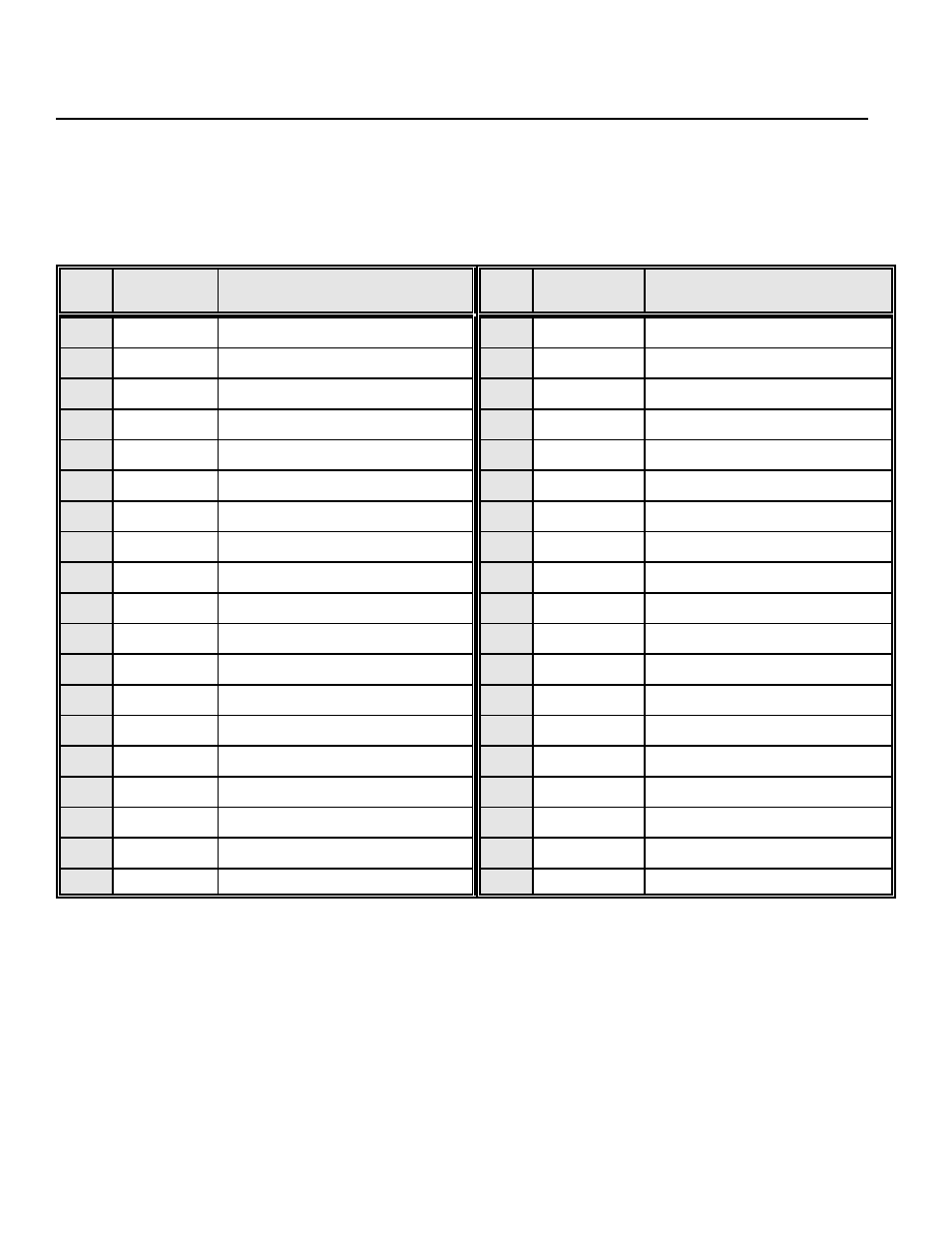
PIN
DESCRIPTION
PIN
FUNCTION
DESCRIPTION
FUNCTION
1
+5VDC
5 VOLT DC OUTPUT
20
A:HOME+
A: + HOME LIMIT SWITCH
2
OUT1
OUTPUT 1
21
A:HOME-
A: - HOME LIMIT SWITCH
3
OUT2
OUTPUT 2
22
A:HARD+
A: + HARD LIMIT SWITCH
4
OUT3
OUTPUT 3
23
A:HARD-
A: - HARD LIMIT SWITCH
5
OUT4
OUTPUT 4
24
0 VDC
O VOLT DC REFERENCE
6
OUT5
OUTPUT 5
25
B:CLOCK
B: CLOCK
7
0VDC
0 VOLT DC
26
B:DIR
B: DIRECTION
8
IN1
INPUT 1
27
B:EA
B: ENCODER CHANNEL A
9
IN2
INPUT 2
28
B:EB
B: ENCODER CHANNEL B
10
IN3
INPUT 3
29
B:EZ
B: ENCODER CHANNEL Z
11
IN4
INPUT 4
30
B:SOFT+
B: + SOFT LIMIT SWITCH
12
IN5
INPUT 5
31
B:SOFT-
B: - SOFT LIMIT SWITCH
13
A:CLOCK
A: CLOCK
32
B:HOME+
B: + HOME LIMIT SWITCH
14
A:DIR
A: DIRECTION
33
B:HOME-
B: - HOME LIMIT SWITCH
15
A:EA
A: ENCODER CH. A
34
B:HARD+
B: + HARD LIMIT SWITCH
16
A:EB
A: ENCODER CH. B
35
B:HARD-
B: - HARD LIMIT SWITCH
17
A:EZ
A: ENCODER CH. Z
36
0 VDC
O VOLT DC REFERENCE
18
A:SOFT+
A: + SOFT LIMIT SWITCH
37
NC
NO CONNECTION
19
A:SOFT-
A: - SOFT LIMIT SWITCH
DB37 PINOUT FOR AXES A & B
+5VDC
This is the +5VDC supplied by the computers power supply. See your Computer Manual for the specifications regarding
this pin.
CLOCK SIGNALS
This is the signal that will be connected to the Step Motor Driver. The driver will take one step for every clock pulse sent
to it. For instance, if a pulse train of 1000 pulses is sent at 50 Hz (50 clock pulses per second) to the driver the step
motor will go 1000 steps, and will take 20 seconds. The output clock is TTL/CMOS compatible. The source current rating
(Voh = 2.7 V) is 12mA. The sink current rating (Vol = 0.5 V) is 9mA. The clock signals are negative going.