Installing the ccm appliance, Figure 2.2: ccm4850 appliance back panel – Avocent CCM4850 User Manual
Page 18
6 CCM4850 Installer/User Guide
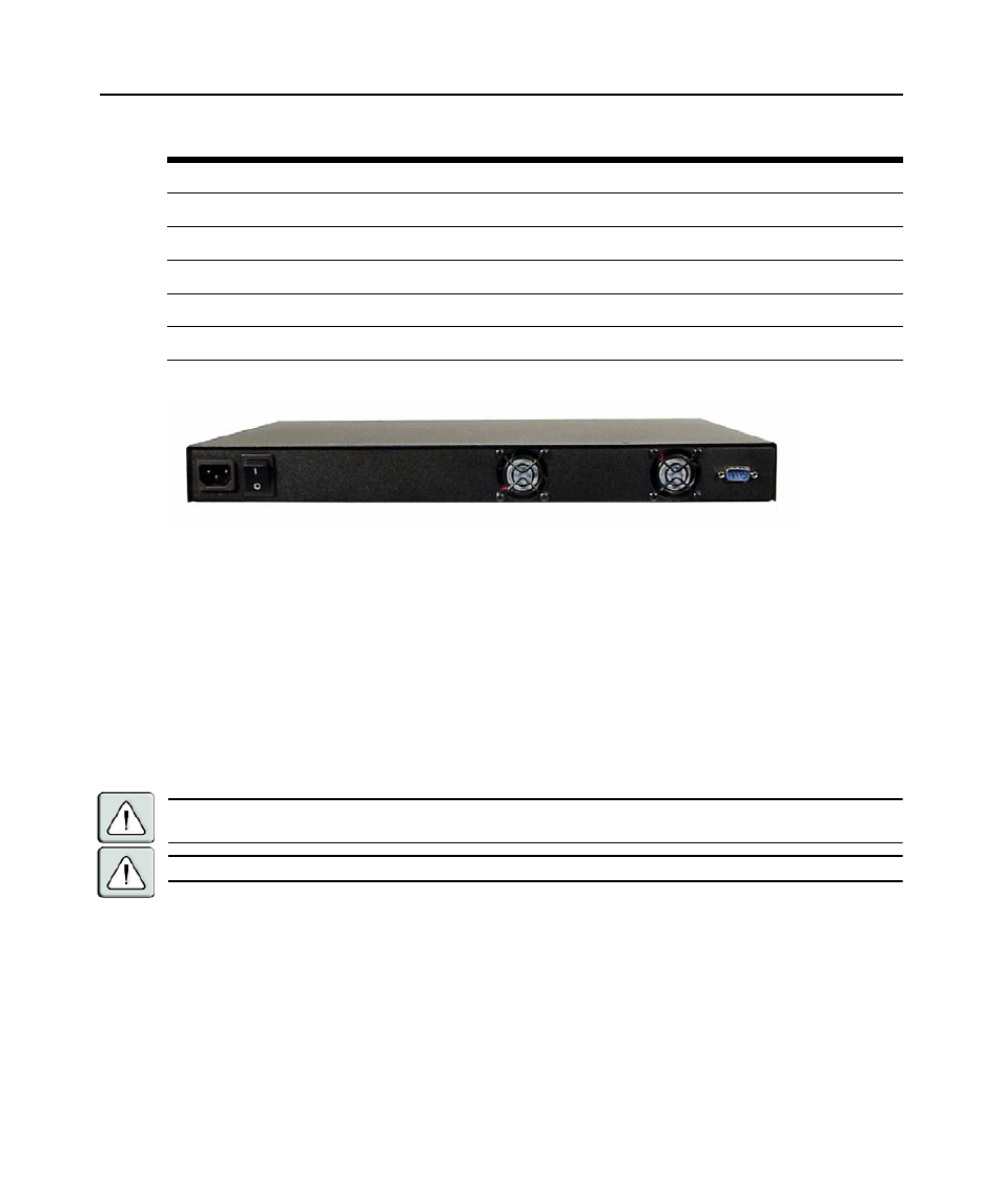
Figure 2.2 shows the back panel of a CCM4850 appliance.
Figure 2.2: CCM4850 Appliance Back Panel
The back panel contains:
•
The AC line cord connector.
•
On/off switch (
O
= off,
|
= on).
•
Outflow openings for the two internal fans.
•
A DB-9 DEBUG PORT connector. This port should be used only on the advice and with the
guidance of Equinox Technical Support.
Installing the CCM Appliance
WARNING: This unit is not user serviceable. To avoid electrical shock, do not attempt to open the unit or operate
with the cover off. Do not attempt to make any repairs. See Appendix E on page 81 for information.
WARNING: The power outlet should be near the equipment and easily accessible.
To install the CCM appliance hardware:
1. Place the unit where you can connect cables between the serial devices and the CCM serial
ports, and where you can connect a LAN interface cable between the Ethernet hub or switch
and the CCM LAN PORT connector.
2. Connect serial devices to the CCM serial ports; see Device Cabling on page 73 for cable infor-
mation. Connect each serial device to its appropriate power source, following the
device’s documentation.
Green
On
Link at 100 Mbps
Orange
On
Link at 1000 Mbps
Off
Flashing
Traffic at 10 Mbps
Green
Flashing
Traffic at 100 Mbps
Orange
Flashing
Traffic at 1000 Mbps
Table 2.1: LAN LED Values (Continued)
SPEED LED
LINK/TRAFFIC LED
Description