Installation and configuration, Hardware overview, Chapter 2: installation and configuration – Avocent CCM4850 User Manual
Page 17: Figure 2.1: ccm4850 appliance front panel, Table 2.1: lan led values
5
CHAPTER
2
Installation and Configuration
Hardware Overview
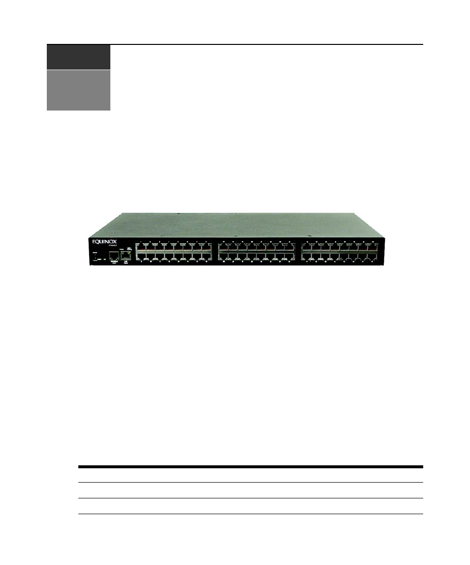
Figure 2.1 shows the front panel of a CCM4850 appliance.
Figure 2.1: CCM4850 Appliance Front Panel
The front panel contains the 48 serial port connectors. The lower left area of the front panel
contains the following LEDs, buttons and connectors:
•
The ONLINE LED illuminates steadily (not blinking) when the CCM self-test and initializa-
tion procedures complete successfully.
•
The POWER LED illuminates when the CCM appliance is connected to a
power source and the power switch is on (|).
•
The RESET button reboots the CCM appliance when pressed.
•
The INIT button restores the CCM factory defaults when pressed and held. See Reinitializing
the CCM Appliance on page 9.
•
A console device may be connected to the RJ-45 CONSOLE PORT.
•
A 10BaseT, 100BaseT or 1000BaseT interface cable may be connected to the LAN PORT.
•
Two LEDs adjacent to the LAN PORT (SPEED and LINK/TRAFFIC) indicate the link speed
and whether there is traffic on the link. Table 2.1 describes the possible values.
Table 2.1: LAN LED Values
SPEED LED
LINK/TRAFFIC LED
Description
Off
Off
No link
Off
On
Link at 10 Mbps