4 attachment control lever and cable, Figure 21 – Ariens 939 SNO-THRO 939001 User Manual
Page 21
6 - 21
6.4 ATTACHMENT CONTROL LEVER AND
CABLE
Attachment Lever
1. Remove jam nut and flat washer from bolt.
2. Remove bushings and torsion spring.
3. Remove retaining ring and traction cable
4. Remove clutch lever.
5. Assemble, using reverse procedure. Attach cable
to bolt during assembly.
6. Adjust clutch lever position if necessary (see
“Attachment Clutch/Brake Adjustment” on
page 18).
Attachment Cable
1. Remove clutch lever from upper handlebars (See
preceding Attachment Lever for procedure.)
2. Slide cable off bolt.
3. Disconnect cable spring from control under frame.
4. Check parts for wear or replacement.
5. Assemble, using reverse procedure.
6. Adjust clutch lever position if necessary
(see“Attachment Clutch/Brake Adjustment” on
page 18).
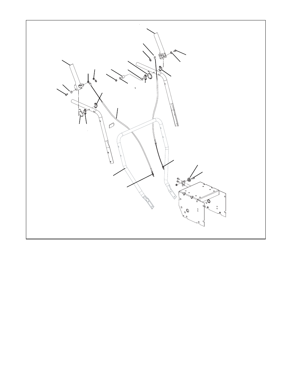
Figure 21
1
2
4
2
3
4
6
5
2
8
9
10
11
12
2
7
13
7
7
8
14
14
15
16
17
7
1. Bolt (2-1/2")
2. Flange Bushing
3. Clutch Lever (Right Hand)
4. Jam Nut
5. Flat Washer
6. Sleeve Bushing
7. Bushing
8. Torsion Spring
9. Retaining Ring
10. Traction Cable
11. Clutch Lever (left Hand)
12. Bolt (3-1/4")
13. Attachment Cable
14. Spring
15. Pulley
16. Bolt w/nut
17. Lower Handle
PS0350-2